What is computed radiography (CR)?
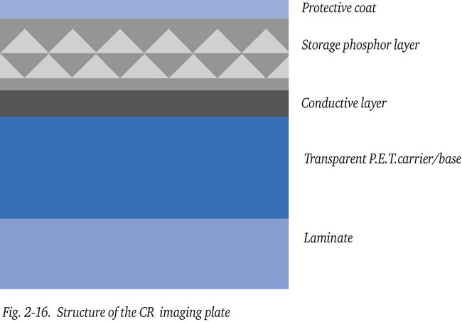
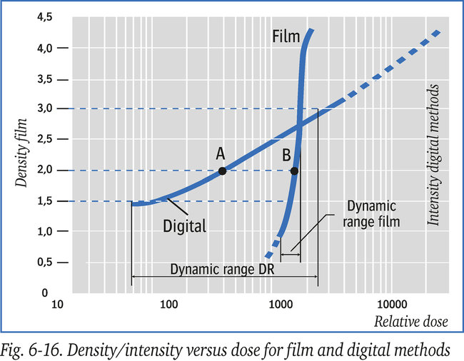
Digital radiography using storage phosphor plates is known as “Computed Radiography” or CR for short. This “filmless” technique is an alternative for the use of medium to coarse-grain X-ray films. In addition to having an extremely wide dynamic range compared to conventional film, CR- technique is much more sensitive to radiation, thus requiring a lower dose, see figures 6-16 and 13-16. This results in shorter exposure times and a reduced safety area. CR is a two step process. The image is not formed directly, but through an intermediate phase as is the case with conventional X-ray films. Instead of storing the latent image in silverhalide crystals and developing it chemically, the latent image with CR is stored (the intermediate phase) in a radiation sensitive phosphor layer. The image information is, elsewhere and later, converted into light in the CR-scanner by laser stimulation and only then transformed into a digital image. The phosphor layer consisting of fine grains has been applied to a flexible, transparent carrier and been provided with a protective coating. An additional laminate layer mainly determines the mechanical properties such as flexibility which is, however, not as flexible as that of an X-ray film. Figure 2-16 shows the layered structure of this type of plate, which is generally called an imaging plate or sometimes wrongly called imaging screen. Note: Screens in the world of NDT, made of lead or another metal, are used to intensify the effect of incident radiation or to reduce the effect of (scattered) radiation.
As a result of incident X-ray or gamma-ray radiation on the storage phosphor, part of its electrons are excited and trapped in a semi-stable, higher-energy state. This creates the latent image. These trapped electrons can be released again by laser beam energy, causing visible light to be emitted, which can then be captured by a PMT (Photo-Multiplier Tube). The wavelength of the laser beam and that of the visible light generated are of course different to separate the two from each other.
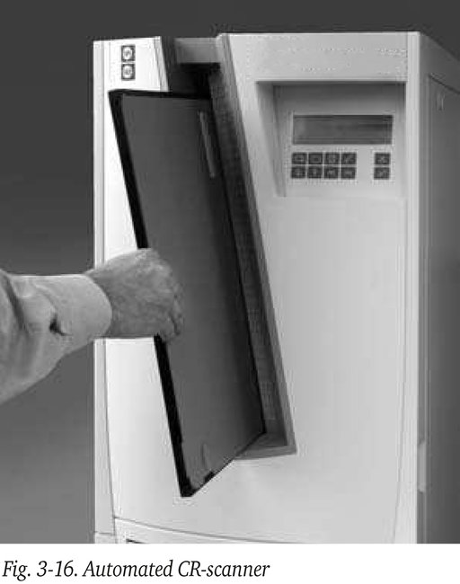
Scanning (development) of the latent image is performed by a laser-scanning device, containing the PMT and its electronics, which digitizes the analogue light signal that is generated. This process takes place in the phosphor scanner, or so called “CR-scanner”. There are various types of scanners. In the most professional scanners, all that needs to be done is to insert a cassette in the input tray and the machine automatically completes the processing cycle. When this process is completed including erasing the latent image the cassette is released from the CR-scanner and ready for re-use. Figure 3-16 shows a typical tower type - mansize - automated scanner.
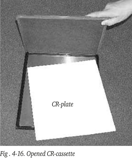
In smaller and portable desk-top scanner models intended for use at remote locations e.g on offshore platforms, the CR imaging plate is manually removed from the cassette and inserted into the scanner, which slightly increases the risk of the plates being damaged. To this end the cassette can be opened, as shown in figure 4-16.
CR-plates can be exposed to subdued light for a few minutes without any consequences for image quality. The scanned image is ultimately made visible on a high-resolution monitor (computer screen) of the workstation, see figure 18-16.
The plate is scanned in a linear pattern identical to the formation of a TV-image. Depending on the line distance selected, typically 50 or 100 micron, scanning speed is 5 to 10 mm per second. This is similar to the speed for digitisation of a radiograph. In the scanner, the latent image is not only read but also subsequently erased (reset), and therefore the CR-imaging plate is immediately available for the next exposure.
The somewhat flexible CR-cassette can be re-used many times ( > 1000 times), provided it is handled with care. Cassettes are available with or without lead screens.
Those developed especially for the NDT-market have built-in intensifying lead screens at the source side, and a second lead screen at the back to absorb radiation caused by backscatter. These multi-layer cassettes are not flexible anymore but can be re-used more often than the flexible cassettes (several 1000 times).
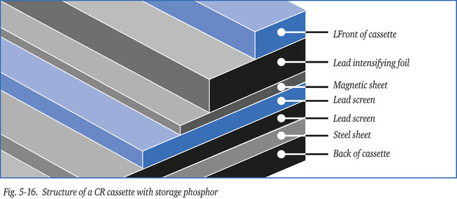
Figure 5-16 shows a cross-section of the CR-imaging plate in a cassette. The steel and magnetic plates ensure that the various layers are pressed evenly and closely together.
The phosphor-crystals on a CR-plate react almost linearly to incident radiation while with a conventional film the silver-halide crystals react exponentially, see figure 6-16. As a result the dynamic range of a CR-plate is much wider than for conventional film, which makes exposure times less critical, reducing reshoots (retakes), and allows various material thicknesses to be examined at the same time. Furthermore, dose sensitivity (speed) is five to ten times higher as well, compare point A and B at a density of 2 (see also figure 13-16) allowing shorter exposure times or weaker sources, reducing the controlled area, or even for some thin wall exposures apply other sources, e.g. Iridium192 to replace Cobalt60, which can be an advantage from a radiation safety point of view. Unfortunately, the image quality reduces. Iridium192, with a lower energy than Cobalt60, requires a longer exposure time and this in turn reduces the image quality due to the larger quantity of scattered radiation.
Note: CR-plates are more sensitive to this scatter (more noise) than conventional film.
For on-stream applications Iridium can replace Cobalt for pipes with a diameter up to 6” (150 mm), with still an acceptable image quality, or even 8” (200 mm) in case of thin wall pipe. The general rule is: the shorter the exposure time the less the scatter thus the better the image quality.
Due to ongoing improvement efforts the relative image quality of the phosphor plate is, in the meantime, equal to the quality obtainable with a medium-grain conventional X-ray film, see figure 13-16. In fine-grain films, graininess is only a few microns, while in current (2006) phosphor plates this is still considerably more (25 micron).
After exposure the intensity of the stored information, in the then semi stable phosphor layer, decreases over time. Scanning within 1 hour of exposure provides the best results, typically half of the information is lost after 24 hours. Thus to avoid this fading, scanning of the CR-plate should not be delayed any longer than necessary.
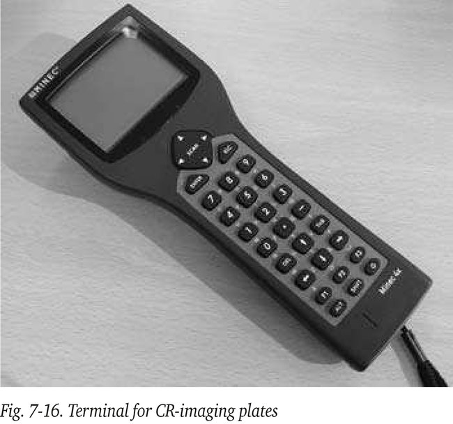
To optimise use of the CR-imaging plates in practice, a small handheld terminal as shown in figure 7-16 has been developed to superimpose specific project- and exposure information to the images. To this end the cassette contains a micro-chip which can receive (wireless) information from the terminal. At site and prior to the exposure the relevant information is sent from this terminal to the micro-chip on the cassette. The specific data are ultimately added to the image in the CR-scanner. Once the data from the micro-chip is erased the cassette is ready for re-use.