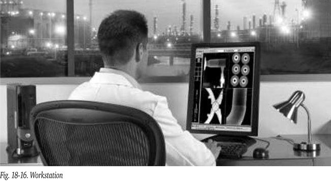
Digital Radiography Workstations
A computer and extreme high-resolution display screen are recommended for digitized films as well as for displaying and processing the images obtained with the CR- and DR-techniques. The number of pixels of the display screen should at least match with the digitization spot- or pixel size of the applied CR- plates or DR- panels to achieve maximum resolution. Radiographic images contain more information than the human eye can discern. For this purpose workstations, as shown in figure 18-16, are used as an “image processing center”. This workstation operates with powerful dedicated proprietary software (e.g. “Rhythm” of GE Inspection Technologies) to manage, process and manipulate images. Images can be manipulated and enhanced in many ways: brightness, contrast, sharpness, noise suppression, rotation, filtering, inversion, colouring, magnification, zoom-pan-scroll, etc. This way, hidden details can be made visible, see figure 12-16 and 19-16. Integrity-procedures should be applied to prohibit possible forgery of digital images.
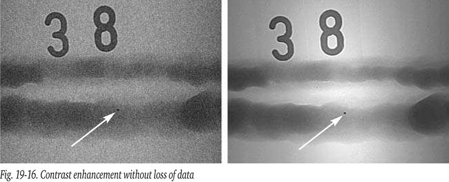
Images can be manipulated and enhanced in many ways: brightness, contrast, sharpness, noise suppression, rotation, filtering, inversion, colouring, magnification, zoom-pan-scroll, etc. This way, hidden details can be made visible, see figure 12-16 and 19-16.
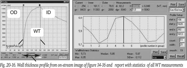
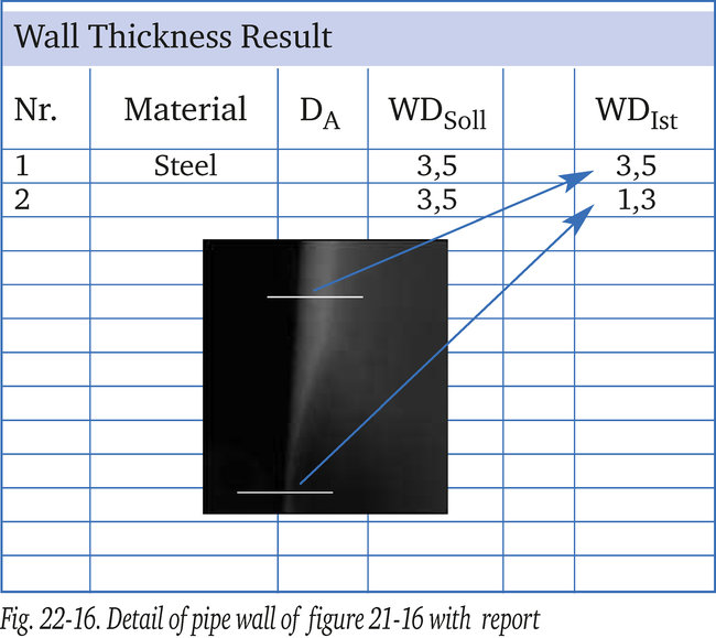
Integrity-procedures should be applied to prohibit possible forgery of digital images. In addition algorithms have been developed for e.g. the comparison of parts of an image with conformance criteria, carrying out dimensional checks (sizing), remaining wall thickness measurements (see figure 20-16), determination of metal loss due to corrosion, defect area measurement, providing image statistics etc. Apart from the original image and its exposure parameters, on a true copy comments and display characteristics (e.g., zoom, contrast, filters) can be superimposed and archived as well. This enables inspection professionals to streamline the process and improve the quality of distributed inspection information.
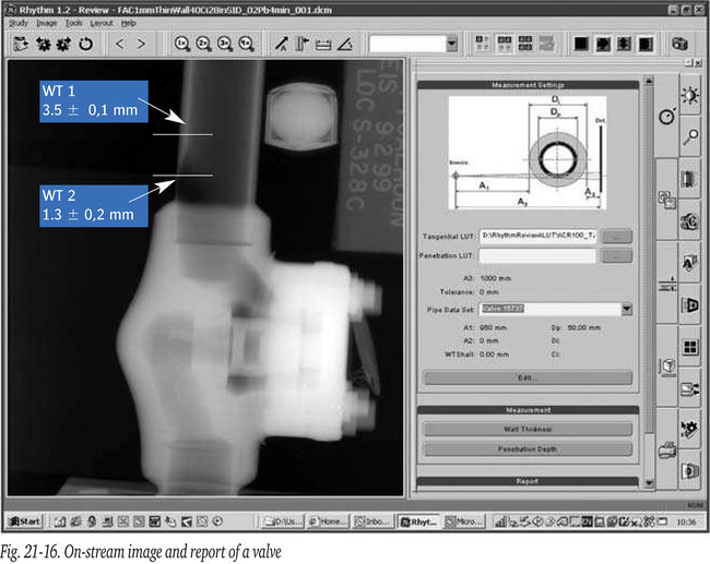
Figure 21-16 shows a screen shot made from the workstation. The screen shows the results of an on-stream exposure on a CR-plate taken of a valve with connecting pipe. The screen shot includes one of the selectable frames of the report module. The image itself shows marks (white lines) superimposed by the operator at the workstation
to establish the remaining wall thickness at those places to be calculated by the software.
Figure 22-16 shows a detail of the selected pipe wall area with the
reported results. This example of a valve with a great variety of wall thicknesses also shows one of the strengths of a digital exposure. If wanted the same image can be used to study the thick wall parts of the valve due to the large dynamic range contained in the image.
Archiving can be done on almost all existing professional mass storage solutions, e.g. CD-ROM up to 700 MB, single layer DVD (~5 GB), double layer DVD (~10 GB) or in the near future, HD-DVD (~15 GB), blue ray disk (~25 GB) and more distant future holographic disk (~300 GB).
Such mass memory capacity of several GB’s (GigaBytes) is needed to be able to store a number of high resolution digital images.
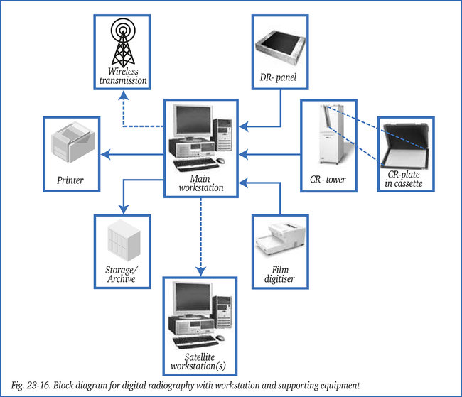
A single image of a ~ 400 x 400 mm panel with a pixel size of 50 micron requires 120 Mb (position and up to16 bit of density data). A pixel size of 100 micron needs “only” 30 MB. The workstation can also transfer images electronically over great distances (through internet, intranet or wireless), which can be viewed, interpreted or stored by remote users on identical satellite workstations. This way information is send to the experts rather than sending the experts to the information. Because the images are digital, multiple copies of the images are always identical. These capabilities are driving the latest trends of enhanced database capabilities and common workstation standards for digital radiography software. Figure 23-16 shows a block diagram of the various components that make up a complete
system for digital radiography.