

Thrust Position Trend Increase on LP Compressor resolved with the Help of System 1

Problem Statement
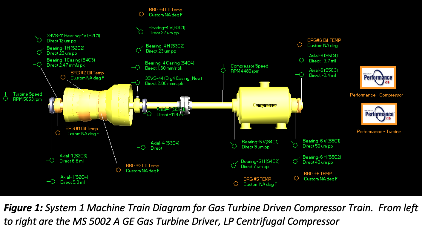
This case study describes the benefits provided by executing our company’s maintenance practices supported by the best condition monitoring platform System1, in one of the Low-Pressure Centrifugal Compressor driven by GE MS 5002 A Gas Turbine in Booster Station BS 150.
Since past 2 years, the Compressor Thrust Position trend was gradually moving towards alarm condition, without any increase in Thrust Bearing Temperature, which was a strange observation. All other vibration and process parameters were found to be normal. Close monitoring was followed, until there was a Preventive Maintenance Opportunity on the Gas Turbine. During compressor inspection it was found that the Thrust Float of the Compressor was high compared to OEM specs. Furthermore, considerable wear was observed in the Thrust Bearing Inboard & Outboard carrier assembly without any damage on the Thrust Pads Babbitt area. Normally an increase in Thrust Float is caused by wear in the Thrust Pads Babbitt area, but in this case, it was not, which makes this case more interesting and unique.
The data was recorded by System1† software, and was later analyzed by KOC Gas Maintenance Support & Reliability Team. We raised the concern with OEM, who in turn recommended for periodic inspection and necessary replacement of Thrust Bearing and its components. This event was an excellent example of how System 1 software is able to capture important diagnostic data in short-term as well as for long-term, aiding in maintenance support.
Method of Approach
Asset Criticality Note: The high-volume LP Gas Compressor is highly critical to the operation of the booster station, due to its status as a unit to support the HP Compressor Unit, and also any major breakdown in Compressor could cause extended downtime of more than 28 days equivalent to 1.42 million KD.
Vibration Data Plots and Analysis
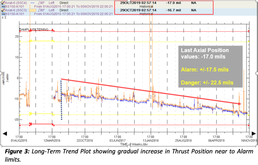
System1 Long-Term data trend Figure 3, showed gradual increase in Compressor Thrust position values nearing to Alarm limit.
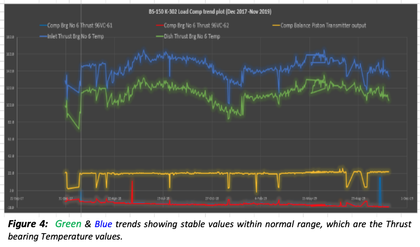
However the Thrust Bearing Temperatures showed no correlation with the Thrust position values and was showing normal trend see Figure 4.
Since there was no correlation between the Thrust position and the Thrust bearing temperature values, and there was already a PM activity opportunity, KOC decided for performing some field maintenance checks on the Compressor.
Field Inspection and Observations: The following were the critical activities performed prior to Compressor Thrust Bearing inspection:
- Thrust Float Checked with Mechanical Dial Gauge, found as high as 24 mils, against OEM Axial Float value Min: 14 mils, Max:20 mils, BN 3500 Alarm :17.5mils, Trip: 22.5mils
- Alignment Checked between Compressor & Power Turbine – Found within tolerance limits
- DBSE (Distance Between Flange to Flange) at Load Coupling was recorded, and found that it was slightly higher than spec, may be due to higher thrust float
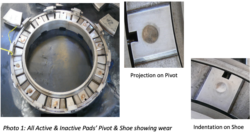
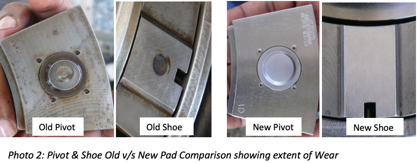
The above activities and observations were further leading KOC to inspect the condition of Thrust Collar and Thrust bearing assemblies. Upon Thrust Bearing Disassembly it was noted that, all the Active & Inactive Thrust Pads back side Pivot and its supporting Shoe in the Carrier assembly was showing wear. The wear depth was up to 4 to 5 mils approximately on each side. This could have accounted for the increased Thrust Float of the compressor.
See below photos 1 & 2 showing the critical observations on the Thrust Bearing Pads:
Root Cause & Remedial Action: KOC approached OEM and there was no specific root cause identified, other than prolonged usage of Thrust Bearings without replacement. However KOC Replaced Complete Thrust Bearing Active & Inactive Pads with Carrier Assembly during this outage. KOC advised for close monitoring and periodic check of Thrust Float in future and replace Thrust bearings if necessary.
The unit was started after the above Compressor activities and Gas Turbine PM activities, and the Thrust position became normal to -5 mils, and showing normal trend.
Summary & Lesson Learned
System 1 platform captured the vital long-term vibration data which enabled KOC to plan and take remedial action in the right opportunity without leading to major failure. Such instances reaffirms the importance of maintaining the Field Instrumentation sensors, Vibration Monitoring System and System1 platform to remain in good health. This drives KOC to include process parameters also into System1 for better trending and analyses in future.
Since the Babbitt Coating should be the first affected component in the Thrust Bearing Assembly, OEM should explore the possibility of improving the Thrust Bearing Carrier Assembly Metallurgical Stiffness to avoid such cases in future.
Such cases gives confidence in operating the machines with conditioned based maintenance philosophy, and also enable sustainable improvement of maintenance practices, and raise the bar towards predictive maintenance philosophy.
Authors
Mr. Abdullah Zaman Al-Merza
Senior Engineer - Equipment Support Gas MS & R
Kuwait Oil Company-KSC
Mr. Padmanabhan Gopala Krishna
Engineer - Equipment Support Gas MS & R
Kuwait Oil Company-KSC
Copyright 2019 Baker Hughes Company. All rights reserved. Baker Hughes provides this information on an “as is” basis for general information purposes. Baker Hughes does not make any representation as to the accuracy or completeness of the information and makes no warranties of any kind, specific, implied or oral, to the fullest extent permissible by law, including those of merchantability and fitness for a particular purpose or use. Baker Hughes hereby disclaims any and all liability for any direct, indirect, consequential or special damages, claims for lost profits, or third party claims arising from the use of the information, whether a claim is asserted in contract, tort, or otherwise. Baker Hughes reserves the right to make changes in specifications and features shown herein, or discontinue the product described at any time without notice or obligation. Contact your Baker Hughes representative for the most current information. The Baker Hughes logo, the Bently Nevada logo, and System 1 are trademarks of Baker Hughes Company.