How do I evaluate reflectors by scanning?
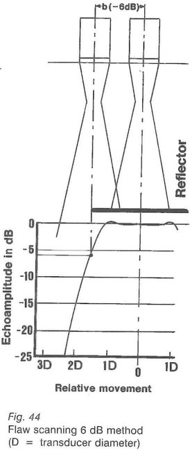
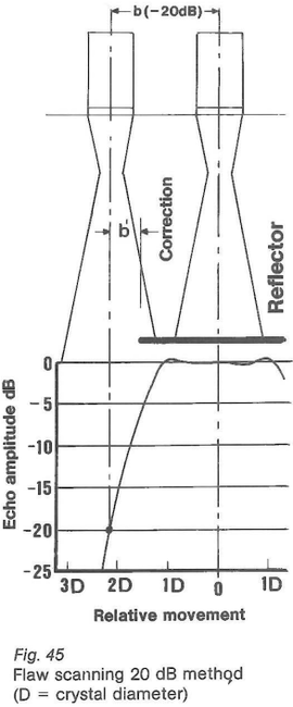
The oldest method of determining the size of a reflector ultrasonically is by scanning lt using the sound beam of the probe. By "wandering around" the reflector its contours can be estimated if this method is used on! Arge flat reflectors (plate test) then the echo indication, as compared to the maximum indication, decreases by exactly 6 dB if half of the sound beam strikes the reflector and half of it passes by (fig. 44). If by moving the probe, one looks for the 6 dB drop-off point then the axis of the beam points directly to 0 the edge of the reflector (half- co value method). The -20 dB method is also used. Here the probe is -5 moved until the indication amplitude has dropped by 20 dB (decrease in amplitude to a tenth of the maximum value) practically to zero. Then the whole of the sound to beam passes by the reflector. If the shift is corrected by the width of the sound beam then one obtains the position of the edge of the reflector (fig. 45). If the reflector small in comparison to the diameter of the sound beam then the half-value method described or the 20 dB method can no langer be used.
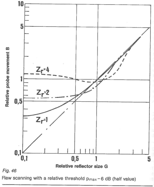
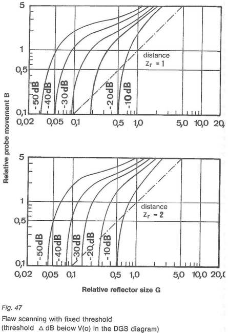
Sometimes however, in such cases even the simple DGS-method leads to unusable results because the distance law of the reflector does not agree to that for a disc. For evaluating such reflectors there are special scanning diagrams for different reflector distan ces (fig. 46, 47). After scanning in two perpendicularly off-set directions the result will be an ellipse using these two dimensions.
Scanning a reflector can be done in two ways: Scanning with relative threshold
First one looks for the location of the reflector which produces the highest echo and then moves the probes to both sides until the echo drops to half the maximum amplitude. This corresponds to a decrease in the echo amplitude by 6 dB. The distance between both these positions is the "half-value extension". lt is determined with the -6 dB threshold relative to the maximum echo. Fig. 46 shows the diagram of flaw scanning with the relative threshold. Normalized sizes are used so that this diagram can be applied in general: the normalized reflector size G, the normalized probe movement B as well as the normalized distance Z (equation 40).
d = diameter of the ellipse (equivalent reflector size) in the scanning direction
b = half-value extension
dj = effective diameter of the transducer in the probe
The following table shows how to use the diagram.
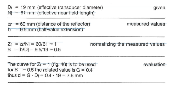
The scanned reflector has an equivalent reflector size of 7.6 mm in the scanning direction. Now the reflector is still scanned in a direction perpendicular to the first scanning direction and estimated in the same manner. Then the ellipse of both the determined equivalent reflector sizes is applicable as the equivalent reflector.
Scanning with a fixed threshold
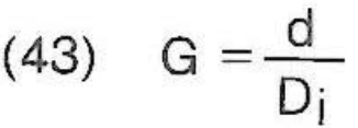
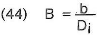
Automatic ultrasonic testing installations cannot search for the location of a reflector which gives the highest echo. Sometimes the discontinuities are so fissured that the highest echo is difficult to find even when testing manually. In these cases lt is recommended that the evaluation be done using a fixed threshold. That distance the probe has moved is measured at which the echo from the reflector remains above this fixed threshold. A monitor can take over the control of the echo amplitudes. Fig. 47 is a diagram for flaw scanning using a fixed threshold: Here too the normalized actual reflector size G (equation 43), the normalized probe movement B (equation 44) and the normalized distance Z (equation 40) are used so that the diagram has a general application. In order to have a universal scale for all probes it is best to relate the position of the threshold to the gain V (0) of the DGS-diagram (fig. 40, 43). The threshold data in the diagram is be understood as follows: V(0) - 10 dB; V(0) -20 dB etc. up to V(0) - 50 dB. The following table shows how to use the diagram.
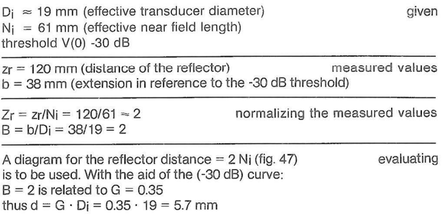
The scanned reflector has, in the scanning direction, an equivalent flaw size of 5.7 mm. If one scans the reflector perpendicularly to the first direction and, in the same way, determines the equivalent reflector size, then the equivalent reflector is the ellipse whose diameters are the established equivalent reflector sizes.