

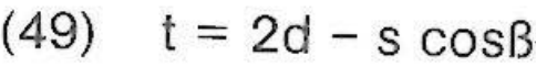
Testing Welds with Inclined Ultrasonic Beaming
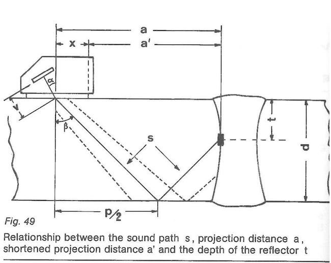
Sound which travels around corners is an every day experience in the audible range. Ultrasound in the MHz range shows however a very high directional effect. This is why special testing techniques are necessary if testing ranges of the test specimen are to be covered in which the ultrasonic waves cannot enter directly. Above all the weld test must settle these difficulties and thus lt is there that inclined beaming is mostly used (fig. 49).
For generating the sound beam which is inclined to the specimen surface longitudinal waves are beamed by means of a wedge. According to chapter 10 and fig. 29 a portion of the radiated pulse is reflected at the interface between the wedge and the coupling medium. A damping element absorbs these interfering waves. When the sound beam enters the test specimen refractio occurs which in general generate; longitudinal and transverse waves (fig. 29).
So that the indication of two types of waves do not cause any confusion one uses almost exclusively transverse waves for inclined beaming. For this the angle of incidence must be chosen so that atter the refraction no more longitudinal waves can occur but however that the transverse waves still can. As per chapter 10 equation (33), (34) this means:
For the frequently occurring combination of plexiglass/steel the following applies:
cp long = 2730 m/s,
cs long = 5920 m/s
cs trans = 3255 m/s
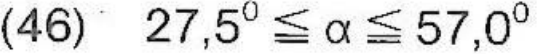
As one has to take into consideration several degrees of angle for the width of the sound beam and similarly a safety distance, the angles used in practical testing are in a smaller interval than as given in equation (46).
The refraction angles ß for equation (46) are:
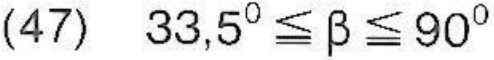
In steel then one should not use a refraction angle of ß 5. 35°. Apart from that already at approx. 70° surface waves occur due to the width of the sound beam (not just at = 90°). Thus, in steel, refraction angles of above 70 ° should not be used on any reflecting surface. Due to the inclined sound path the locating of a reflector from the screen indication (transit time) and the position of the probe (fig. 49) is only possible by a mathematical means. The lower half of the weld is beamed directly - testing is done over the shortest distance and using the narrowest sound beam. There is the following relationship then between the sound path s to the reflector and the depth position t:
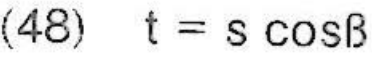
Reflectors in the upper half of the weld are indicated by a reflection from the underside of the test specimen by the longer path shown in fig. 49. Here between sound paths, the depth position t and the wall thickness d the following applies:
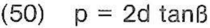
The projection of the full zig-zag path in the wall is designated "skip distance p"
To simplify locating reflectors the shortened projection distance a' has been introduced (also on special DGS dagrams and DGS scales):
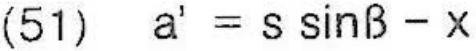
The sound path s to the reflector is projected to the surface of the test specimen and is shortened by distance x between the front edge of the probe and the sound exit point. On the corresponding diagrams and scales one can directly read the position of a reflector in front of the probe and measure lt oft on the test specimen. Transverse waves (shear waves) show different type of mechanics with sound attenuation as is shovvn by longitudinal waves (compression waves). Attenuation for longitudinal waves can thus not be simply converted into attenuation for transverse waves. With most of the common types of steel the attenuation coefficient ß for frequencies f ≥ 3 MHz is:
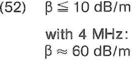
With a reference to the total sound path.
As, when testing using inclined beaming, the reflectors can offen only be detected in one position in which they are not struck perpendicularly by the sound, one must either use the mirror effect (tandem-method, fig. 36) or select non-direction sensitive sound beams i. e. work with the largest wave length possible viz: the smallest possible frequency (see chapter 16). Explanations on the terms of testing with inclined beaming, as well as the way to go about testing are given in [14] and [15] as well as many other recommendations on weld testing.