

The Working Range of Sound Beams
With automatic testing the test specimen is scanned along preselected paths although most probably not all possible flaw locations are located on these paths. For reason of economy the testing is to be done as quickly as possible. One has to accept therefore, that for the evaluation, the highest possible echoes are not available as they are with the manual test. With automatic testing accordingly the same reflectors can be detected with different sensitivities depending upon their position in the sound beam. In this connection remember that the sound field builds up and collapses in cycle with the pulse repetition frequency (chapter 7).
In order that there are no undesirable testing gaps when testing automatically the scanning grid must be adapted to those conditions called for by the sound field and the expected reflectors. lt is not sufficient to establish the scanning paths simply by considering the probe size — the decisive point is the size of the portion of the sound field which is acceptable as the working range.
This working range can be determined for flaw scanning using diagrams 46 and 47. The following example makes lt easier to understand.
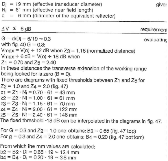
What is the working range when using a probe with Di, Ni taking into consideration the requirement that, within this range an (equivalent) reflector of d = 6 mm is to be indicated with an echo amplitude which is less than 6 dB below the highest possible echo indication?
This requirement means that diagrams must be used for the 6 dB drop with fixed threshold (fig. 47). The distance diagram fig. 40 (DGS) serves for evaluating the pressure on the axis of the sound beam.
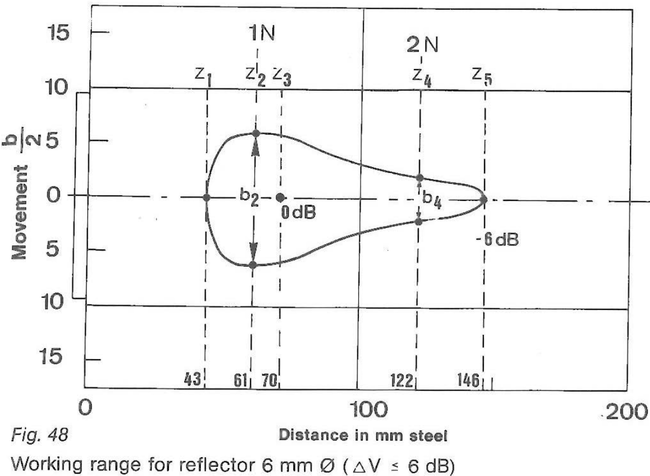
Using the normalized reflector size G one determines the normalized probe movement B for different normalized distances Z. These values are converted into absolute values with Di and Ni. In this way one obtains limiting points of the working range looked for (fig. 48).
lt one draws b2 and b4 symmetrically to the central axis of the sound beam (fig. 48) (b/2 to each side) then one obtains, including points z1 and z5, an enclosed curve which limits the range in which a 6 mm reflector will be indicated by echoes whose difference in amplitude is less than 6 dB. If one does not require the working range (with reference to the volume) but only the width of the working range at a fixed reflector distance Zr then the distance law (fig. 40) does not have to be considered. The width of the range for an echo amplitude drop of 6 dB is obtained directly from the diagram for the relative threshold (fig. 46).
Revolutionizing Gas Turbine Inspection