

Choosing the Right Ultrasonic Probe
Probes should generate sound waves within the test specimen which have specific properties and these waves, under certain criteda, should indicate flawed locations in the workpiece. The probe then must comply to the conditions dictated by the workpiece (material from which it is made, the shape and the test requirements e. g. minimum flaw length). This is naturally only possible provided that the basics of acoustics allows it e. g. a divergence free sound beam would be of advantage for materials testing but unfortunately it can't be realized for physical reasons. What has been shown to be practical is to first establish the testing frequency and then, using this, determine the most suitable size of probe. The test frequency must be in accordance with:
The sound attenuation in the workpiece. Higher frequencies involve higher attenuation.
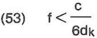
The smallest reflector which is to be detected and the structure of the material. The structure of the material should remain well below the wave length Ä as possible. With an average grain size dk the following formula is recommended for practical testing:
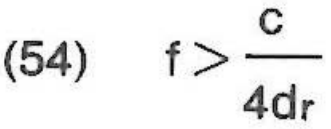
For the smallest reflector dr which still has to be detected the following should apply:
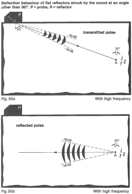
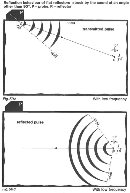
The testing requirements as to the directional characteristics. If flat reflectors are expected which can't always be struck perpendicularly by the sound beam then flaw detection becomes that much more difficult as the frequency increases. The reflector then reflects namely in a preferred direction which no longer points to the receiver probe: the reflector does not cause an indication (fig. 50).
The testing requirements as to the far resolving power. The higher the frequency the betten can adjoining reflectors be detected separately.
Special conditions called for by the type of flaw and the geometry of the work piece. They can be fulfilled by changing the type and the position of one or more sound sources. That is either round or square transducers and flat or focussing types of sound sources, normal or angle beam probes; single crystal or TR-arrangement etc. The TR probes have a very good near resolving power (no dead zone) and thus can detect reflectors which lie very close to the surface of a work piece. Above from that the distance of the noise-to-signal ratio is better in the working range (focal range) than lt is with probes which have single elements. That is very useful with coarse grained structures. The disadvantage is the small working range. By focussing the width of sound beams of probes with single elements can be constricted and this increases the testing sensitivity and the detecting power for the smallest reflectors. The disadvantage is the resulting reduction of the working range. A focussing probe can only scan a very small volume per pulse. Short pulses (those having a wide frequency spectrum) make possible the resolution of very short transit times which e. g. is desirable for measuring well thicknesses. Conversely broad-band pulses react in a very complicated manner on flat reflectors. The reflected pulse ought to be checked for all the frequencies involved (ultrasonic spectroscopy). For equivalent reflector evaluation smallband pulses deliver results which are much more simple to Interpret.
The requirements of the testing sequence. Manual testing calls for the use of probes different to those used for automatic testing. For testing in the production line or with increased temperatures the most suitable couplant media and corresponding design of probe must be selected. When testing materials compromises have continually to be made between a higher probability of detection when scanning (testing at lower frequencies) and a higher accuracy when determining the extension and shape of a reflector (testing with higher frequencies). Also if as in this case, lt is the probe only which is being discussed the chbice applies also to the rest of the entire testing system. The testing equipment consisting of ultrasonic wave generator, probe, receiver, test machine and signal processor is an information system in which, as in other places too, the weaker link determines the quality and the reliability. A probe which is the optimal one for a testing problem also requires an optimal generator, amplifier and evaluating Instrument.