

Orbit 60 Series Update: System Fundamentals - Output Cards


2020 Product of the Year Silver Award Winner: Machinery protection, condition monitoring system
The Orbit 60 from Bently Nevada, a Baker Hughes Business, is a next-generation platform that collects and processes data, equipping operators with the right data and analytics to determine the health of their machines. It is an intrinsically cyber-secure machinery monitoring system with a built-in data diode, which enables secure one-way data transfer from the device to Bently Nevada’s flagship machinery management software System 1 for proactive monitoring and diagnostics.
Introduction
Welcome back for the 4th quarter update of Orbit 60, Bently Nevada’s latest condition monitoring, protection and data integration platform. In last quarter’s update, we discussed how we reduced the number of Input card choices for Orbit 60 from over 80 different card types down to just 10. This was accomplished while simultaneously adding the capability of accepting positively biased sensor inputs such as traditional IEPE accelerometers, and eliminating the need for dedicated Keyphasor input cards*. We expect that these improvements will make ordering and configuration of the system significantly easier for our customers. They should also reduce the required spares by half as well.
* A dedicated High Speed Keyphasor is still recommended when rotor speeds exceed 12,000 rpm.

In this update, we will discuss the various enhancements that we have made to our Output cards. We will also examine how to connect the Orbit 60 to System 1, your DCS/Historian and your remote display(s). Additionally, we will introduce three key trademarks of Orbit 60, Orbit conneX™, Orbit aXess™ and Orbit Xtend™. Each of these capabilities is a unique feature of the Orbit 60 platform.
Key Outputs – Relays, Recorder Outputs, Digital Communications and External Displays
Protection Fault Relay – Instrument Health:
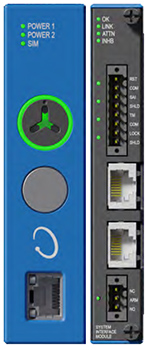
The Protection Fault relay is found on the System Interface Module, SIM. Every Orbit 60 system must contain a single SIM module, as this is the module we use to configure the system. There are several other functions that the SIM module is responsible for, but for the context of this article, we are going to concentrate on the Protection Fault Relay, and later on the display module output.
The Protection Fault Relay functions similarly to the 3500 Rack “OK”/Protection Fault Relay in that if there is an actual protection fault it actuates. In Orbit 60, this relay is of the digital variety, and can accommodate a load of 100 mA, 125 Vdc.
With Orbit 60, we weren’t satisfied with just being able to warn of a Protection Fault, we wanted to also be able to provide more proactive information about the monitoring system. So, instead of having only two states – OK, and Not OK, Orbit 60’s improved version, provides more actionable information with additional states:
- OK – All input signals are within limits, and there are no system faults detected
- Protection Compromised – this could be either a failure of one of the two power supplies, or the impending failure of a module used for protection. For example, if one of the three ethernet cables connecting two bridges modules has been compromised, the system will continue to function as desired. However, there is still a fault within the system that could affect its protection capabilities.
- Protection Fault – This represents a complete failure of a protection path. As an example, this might be a sensor that is used for protection that has gone “Not OK.”
- Attention – This status is present when either a Protection Fault or Protection Compromised event occurs. Further details would be found in the System Event list.
The Attention and Protection Compromised states are not tied directly into the Protection Fault relay, but are statuses on the System Interface Module. It is recommended that the Protection Compromised status be incorporated within your relay logic, to alert you when there is a potential fault in the system. It should also be understood that because they are statuses, they are also available in System 1, and can be exported from Orbit 60 directly through Modbus. An LED on the front and back of the rack will also light when “attention” is activated.
Speaking of extra condition monitoring information we are providing for the system, the System Event List also contains whether a module has failed, or if the wiring needs to be checked. Diagnostic information such as what is wrong with a failed module, the temperatures of modules, supply voltages and how long a module has been operating is also provided.
Relay Modules:
Relay Modules are certainly an important component in any protection system. It is the relays, after all, that send the signal to the control system to shut the machine down. In Orbit 60, we have designed two different types of relay modules. While they both utilize the same voting logic, they have different actuation methods. . The first is the traditional electromechanical relay, which is used when driving a load greater than 100 mA through interposing relays (or a direct load of less than 100 mA), while the other is solid state which is compatible with the low current draw of most modern ESDs using digital control systems. Both can be configured using TRUE AND, NORMAL AND, NOT, and OR voting logic.
The Protection Processing Module is the brains of the Orbit 60 system, and is where all of the alarm statuses are developed. The Relay logic can also use OK/Not-OK statuses from any module in the system, the protection fault statusses discussed earlier, as well as the process data from the Communications Gateway Module (i.e. from your control protection states).
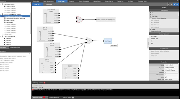
Relay Configuration is accomplished via the Orbit Studio configuration software. The configuration process is very visual, and while we could spend a page or two showing you all of its neat features, it is not the focus of this article. The following screenshot however, will give you an idea of how simple and well thought out the relay configuration screen is. It should be noted that this screen will show, and reflect current values. This allows you to visualize how your logic stream is operating, and what components actually caused the relay to actuate.
Before digital controls were developed, relays had to carry somewhat significant electrical currents. For those situations that require carrying an electrical load, we used Electro-Mechanical relays, similar to a light switch that is either open (separated – light off) or closed (joined – light on). With the advent of Emergency Shutdown Devices, ESDs, the need to carry loads was all but eliminated, and in fact the current loads across the contacts were so small, that they required us to gold plate the contacts on the 3500 electro mechanical relays.
The electro-mechanical relay is a double throw relay, which supports a voltage range of 5Vdc to 240 Vac, and can carry a load either directly or through an interposing relay, of between 0.1 to 4.5 amps. Due to the mechanical nature of these relays, this card is one of the few that takes up two slots in the chassis.
The Solid State relay card provides relays that support low current communication applications where the control system is essentially looking for a one or a zero. It can handle voltages up to 125 Vdc. The digital relay module only takes up one slot in the chassis.
With the enhanced number of machines, variables, setpoints and relay types, It is possible to have multiple (and multiple style) Relay cards in an Orbit 60 system.
Recorder Outputs:
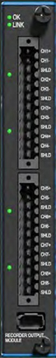
The Recorder Output card is its own separate, stand alone, 8 channel card. As with all of the other input and output cards in Orbit 60, you can have multiple recorder output cards. Outputs include the standard 4-20 mA as well as 1-5 Vdc and 0-10 Vdc options. For example, to make your choices even easier, Orbit 60 will let you have a 4-20 mA output for channel 1, and a 1-5 Vdc output for channel 2 as well as a 0-10 Vdc output for channel 3. This means that there is no need to have two (or three) different i/o cards just to feed different signals to different systems.
While this versatility is powerful, what makes Orbit 60’s recorder output card really stand out is that you can assign multiple values from the same input channel to any of several output channels on the card. For example, you might want to see Accel in g’s on one recorder output channel, Velocity on the next, and displacement on the third. In Orbit 60 this can be accomplished from one transducer input. No need to parallel the signal inputs!
It should also be noted that this card is available for SIL applications.
Buffered Transducer Outputs
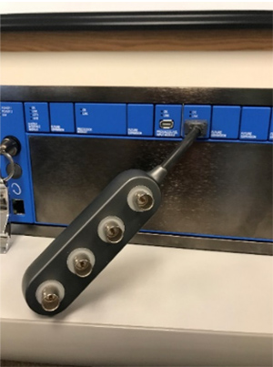
I mentioned in the last article that I started my career with Bently Nevada in the Machinery Diagnostic Services, MDS, group. One of the first things that an MDS engineer likes to do, is hook their ADRE into the BNC connectors in the front of the rack. If you look carefully at the Orbit 60 rack, you won’t find any BNC connections though. That is because of the connector’s size, and the miniaturization of the rack itself. What we do have though, is a modern interface that connects to a BNC dongle on either the front or the back of any of the input cards. As in our past racks, these signals are unconditioned and buffered. You will not be able to affect monitor values by plugging in – even if you are plugging in a function generator.
Digital Communications
There are three output modules that are specifically concerned with digital communications. The first is the Communications Gateway, CGW, which is used for two-way, secure communication with your control system. The second is the Condition Monitoring Module, CMM, which we use to communicate with System 1. The third is the Bridge Module, which is used to connect multiple Orbit 60 racks together.
Communication Gateway Module, CGW
You may be familiar with the 3500 System’s Communication Gateway (3500/92). It provided measurements, alarm setpoints, alarms and statuses through Modbus or EGD protocols (either serially or over ethernet) to your DCS or historian. The Communications Gateway in Orbit 60 does this, and more.
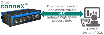
Due to our inherent cyber secure design, we can also use the Orbit conneX™ architecture on the Communications Gateway to integrate with your control system, HMIs and even your historian.
Having this information within the system gives the Orbit 60 several advantages:
- It can use statuses or process information to:
- Change alarm levels – i.e. if the system knows that the machine is operating in a particular state, it can adjust alarm levels to those that you have previously specified for that state
- Data can be sent securely, through the Condition Monitoring Module to System 1 for more complete diagnostic capabilities, or for use in System 1’s HMI display
- Process Data can also be made safely available via the Orbit 60 on your business network without having to use complex firewalls or data diodes. This is done by retrieving data through the Communication Gateway Module and routing it through the Condition Monitoring Module.
Condition Monitoring Module, CMM

The Condition Monitoring Module, CMM, is one of the other digital communications module in the system. The CMM is able to read all of the information contained on Orbit 60’s backplane. However, with our Orbit aXess™ communication method, it is NOT capable of writing anything onto the backplane! This is what enables the Orbit 60 to have a cyber secure connection to System 1.
Having this capability is a great advantage, with one of the not so obvious advantages being that you can still alter how the CMM collects data without having to go to the rack and change configurations. This means that if you want to collect a 3200-line spectrum instead of a 800 line spectrum, you can make that change request in System 1 – at your desk, and it will be implemented down at the CMM immediately.
The CMM has on-board Solid-State memory which can hold several days’ worth of data. This means that if you lose communications with System 1, and it can’t be restored for a few days, you won’t lose your data. It also means that if you don’t have the system connected to System 1, and your unit trips, you can still have an MDS engineer come out and retrieve and analyze that data, even if you try to restart the machine a few times before they get there.
The CMM has read only access to all the measurements, waveforms, system configuration, alarm and events logs as well as the process data brought in by the communications gateway.
As with all the other output modules, it is possible to have more than one CMM. There are a couple of scenarios where this could be extremely valuable. One is where you use one CMM for your in-house System 1, another that goes to the OEM’s Remote Monitoring Center’s System 1, while a third module could be used to get data back to Bently Nevada’s HOST platform for remote diagnostics and support. Additionally, one can cyber-securely connect the CMM to a cellular modem, so there is no need for extra internet infrastructure!
Bridge Module

The Orbit Xtend™ architecture allows multiple Orbit 60 racks to be connected to build a system. This innovative architecture unlocks field or remote I/O deployments to significantly reduce overall installation costs. The bridging capabilities of Orbit 60 essentially extend the digital backplane from one rack to any racks bridged together. Data is replicated across the racks real-time and fully supportive of machinery protection and/or condition monitoring applications. There will be a detailed Orbit article in the future on the bridging capabilities of the system or request the bridging concepts whitepaper at the bottom of this article.
External Displays
The SIM, or System Interface Module, as mentioned previously, has several functions, one of which is to provide data to the display.
Available display pages include:
- Channel and Module Data – This data is presented in color coded bar graph format and displays each channel’s primary measurement (overall values with alert and danger settings, or relay statuses for example). 1X and 2X amplitude and phase can also be displayed, along with any other trended variables that you have configured.
- Trends, Waveforms and Spectrums for all of the inputs – including the Keyphasors®!
- System Event List – This helps you understand the health of your system, and when various events, such as system resets, power loss, configuration changes occurred.
- Alarm Event List – Similar to the System Event List, this list deals solely with the various alarms. For example, this list would be consulted to determine which channel was “first out” on an alarm event.
- Alarm and OK Status – Use this screen to perform a quick check on transducer and monitor health statuses and alarms
- Relay Logic maps – This screen will show the logic and statuses associated with each relay. We have made great improvements with this screen, as it will show, very intuitively, alarm levels, and which channels have triggered the alarm logic.
There will be nine custom display page options as well. These display pages will be created using the same Orbit Studio software used for system configuration. With this software, you will be able to create custom screens including machine train groups as well as system wide data.
The external displays are driven through a small industrial computer connected to the SIM via ethernet cabling. This means that you can mount the display where it makes the most sense. It also means that you can have multiple displays as well, so it’s possible to have a display at the machine and another in the control room if desired.
The three external displays we offer are 120M8155-01 (10.4” display), 120M8155-01 (15” display), and 150M1466 (21.5” display). The 10.4 inch version is certified for use in hazardous environments. If you already have the latest version of our 3500/94 display, it will interface with Orbit 60.
In our second system release, we are planning on having a display that mounts directly to the front of the 19-inch version of the chassis. While not available upon first release, it will be backwards compatible and work with first release systems.
More information is available on our website:

Orbit 60 milestones
Fall 2019 – Public disclosure and new product announcement (ATD)
Spring 2020 (April) - Available to quote (ATQ) fixed price proposals
Spring 2021 (April) – Available to ship (ATS) API Turbomachinery and plantwide applications
Summer 2021 (August) – Available to ship (ATS) TSI and Bridging applications
Next Steps
Our teams are excited to discuss Orbit 60 in more detail, we have multiple technical white papers available for a deeper dive into the following topics. Please reach out through the contact us link below to receive a copy and we will connect you with your local expert.
- Orbit 60 Series or 3500 Detailed Comparison - This document details the difference between Bently Nevada’s Orbit 60 Series machinery protection system and the 3500 system.
- Orbit 60 Data Security Condition Monitoring Module - This document is intended to describe how the Condition Monitoring Module in the Orbit 60 Series Monitoring System provides a secure solution with full high-resolution data to external networks without jeopardizing the operation of the protection functions.
- Orbit 60 Series Bridging Concepts - Bently Nevada introduces the concept of bridging with the Orbit 60 Series system architecture.
Learn more about Orbit 60
Product Video - Orbit 60 Teaser
Product Video – Orbit 60 Full length
Orbit 60 Series and System 1: Bloomberg TV
Houston Chronicle: Bently unveils the Orbit 60
Turbo Machinery Magazine – Bently Nevada’s New Platform
Q1 2020 Orbit Article – Introducing Orbit 60
Q2 2020 Orbit Article – Available to Quote – Explore the Cost Savings
Q3 2020 Orbit Article – Now – Less Spares!! – How to Choose Input Modules
Our Experts

Tarannum Sarang
Senior Product Manager

John Kingham
Strategic Field Application Engineer
BIO
Mr. Kingham has been involved in the rotating machinery realm for more than 35 years. He started with Bently Nevada in 1986 as a Machinery Diagnostics Engineer, where he diagnosed machinery problems based upon their vibration characteristics.