

Bently Nevada's Design & Installation Services: Removing blind spots and driving Digital Transformation

Reliability Managers are challenged to ensure safe and cost-efficient operations & maintenance (O&M) on their plantwide industrial assets. This is the niche where a well-positioned specialist such as Bently Nevada (BN) can supply a broad list of packaged solutions that will place customers closer to their Digital Transformation (DT) via a multiyear roadmap of investment options.
Generally, DT transformation seeks to maximize only the use of existing asset data, and often neglects to focus on those assets where data is currently not collected. In many cases, these data blind spots are on the long time "bad actors" in the plant, that can be responsible for maintenance related downtime headaches that hinder efficient production. For an industrial operation to run at optimum performance, key asset performance measurements are required to understand the underlying issues impacting asset behavior. Blind spots in asset coverage hinder the success of the desired outcomes of DT Initiatives.
Bently Nevada's Design & Installation Services (D&IS) is tailored for these unmonitored assets. It is more than just retrofit services for industrial asset vibration condition monitoring and offers in a true sense "Peace of Mind" for customers via a one stop lump sum turnkey (LSTK) solution for enhancing asset availability and reliability plantwide.
Bently Nevada understands customer's needs to increase rotating and reciprocating asset protection, reliability, and availability; driving them to achieve higher mean time before failure (MTBF) metrics on machinery with the application of new analytic capabilities and asset specific machinery diagnostics based on global standards such as API, ISO, and our proven Best Practices. Our extensive machine knowledge capabilities are combined with domain expertise to mechanically modify unmonitored machines, ranging from installing a case mounted transducer to a full modification of the bearing cover to have proximity probes penetrate the housing and directly observe the rotor.
- Every asset in plant has potential to improve O&M profitability.
- Increasing need of Smart Measurement for the Digital twins analytics to monitor and manage active risks.
- D&IS is the key enabler for customer's Digital Transformation Journey by providing real time visibility of "Active Risks" of operation and optimize "Asset Maintenance Strategy".
- Retrofit projects needs to be done right first time, and BN with 60+ years of application expertise, experience and skills are best placed to do this.
BN's expertise extends across a broad number of asset types such as reciprocating compressors, steam and gas turbines, motors & generators, centrifugal compressors, pumps, wind turbines, extruders, hydro turbines, and their special applications in various industries. All these application-specific measurements are connected to state-of-the-art condition monitoring and protection systems that collect data either via continuous monitoring systems (like Orbit 60, 3500, 2300 or 1900 series field monitors etc.) or online periodic systems (like Trendmaster DSM, vbOnline Pro etc.) based on asset criticality and classifications.

Expertise and offering
- Lumpsum turnkey (LSTK) capabilities providing end-to-end solutions to customers as one-stop shop.
- Offering the best solution, based on the knowledge of industrial standards and our recommended best practices.
- New or retrofit applications, single machine, or Plantwide
- Scope based on Customer needs, from 100% turnkey to coordination internal plant resources for selected Project-design-only services upon request.
- Able to accommodate tight turnaround schedules and outages.
- Complete Installation specific documentation on System design and Project management including preliminary for approval, issued for construction and as built: electrical (wiring diagrams, JBs, field cabling) and mechanical (machine modification, bracket design and sensor Installation/hook up drawings).
- Engineering services for all necessary Machinery modifications, to decide the right kind of instrumentation, Brackets design, mounting locations specific to assets, cable routing, junction boxes, cabinet and all project related to asset retrofit.
- Site supervision of mechanical and electrical sub-contractors on modifications and Installation.
- Work closely with Machinery manufacturers to ensure safety a compatibility of modifications.
- Compliance with hazardous area requirements, and country specific certification agencies.
- System-specific training, on-site or in one of our global training facilities.
- Factory and acceptance test.


Asset retrofit for enhanced condition monitoring
Why?
The term "old machine" starts many investment discussions in industrial plants on how (or if) to instrument and collect data on them. In many plants, an old machine it is just an excuse for justifying no proper maintenance being done on them, and for those that are maintained, the monitoring frequently does not comply with API 670 requirements for machinery protection systems, which is the most demanding protection monitoring standard that many insurance companies expect as the basic level of protection and preventive measure against unexpected failure or downtime. The reason behind placing a Standard as framework, is to set the basic reference points to guide many top tier organizations for investment prospective in early diagnostics and to employ in-house know-how in order to achieve the optimal level of reliability and pertinent maintenance practices, as a direct result of improved machinery health monitoring and diagnostics.
Retrofitting a machine or a machine train, enables the huge stream of information that along with metadata, will provide analytical insights into the asset's health such as its dynamic performance. Such data is then used by experts and evaluated against many of the Key Performance Indicator (KPIs) within the APM software.

When?
Retrofit projects are usually arranged quite far in advance of a planned outage of a UNIT/Machine section. It is ultimately an alignment between BN's and customer's project engineers.


During this stage of the process, the customer presents a desired time window with milestones, which are then aligned with BN's delivery schedules of parts to install and the needed services interventions.
Following BN's project-based process, once the sale is set and the purchasing order in place; the D&IS field engineer starts designing the installation of each measuring point on the machine, considering all those supporting brackets, and the connecting and routing means that will be required to place each monitoring point from the machine to the junction box, and then to the cabinet, where the Machine Monitoring System (MMS) is.
OEM limitations, customer prerogatives, considerations, and approvals; HSE, planning, site coordination meetings, subcontractor supervision and adherence to BN Best Practices, technical documentation, are common and expected activities of the project execution, that must be performed in line with our internal Quality Management policies, the spirit and letter that rules each project.
How?
The most logical choice when making the decision on which assets to monitor regularly, is to retrofit all those process critical machines, or those associated with bottle necks or those with decreasing performance, that can't easily catchup with production demand levels. Specifically, those critical machines impacting the business will be the driving factor for retrofitting.
Machines are instrumented by the API 670 criteria, which relies on the diagnostic use, but is finally the machine's morphology and mounting possibilities which limits the number of instruments to address all possible and known machine faults and malfunctions that produces asset deterioration.
To explain it further, let's consider a journal bearing on any rotating machine. To enable condition monitoring on the machine, a proximity probe needs to be installed.
A basic design review proceeds as follows:
- First, all geometric, functional, and possible safety issues are evaluated specific to the asset's application and role in production.
- Second, identify the appropriate location and design needs of the mounting bracket/s and create a design that best addresses capturing a vibration response away from bracket resonance. The ideal installation becomes a mixture of what known best practices recommends, OEM preferences and/or the customer's prerogatives based on machine failure history.
- Third, configure the installation to achieve (by redundancy), the degree of logical protection required by the customer.
- Forth, consider electric design and compliant related mechanical enclosures.
- Finally, everything is documented and thoroughly reviewed with the customer prior to a definitive Bill of Materials and further details around retrofit scope & outage schedule. At this stage, an OEM recommendation is often sought related to mechanical modifications and design details.

As the saying goes, more sugar makes the coffee sweeter. Likewise installing the optimal amount of instrumentation based on the asset's application is required to capture the correct amount of data to enable comprehensive diagnostics.. E.g. proximity probes for the relative vibration, Velomitors for absolute bearing vibration (one or maybe two for redundancy to avoid signal loss until next planned outage), RTD/ Thermocouple, for bearing metal temperature, keyphasor to have speed & synchronous signals, tachometer for overspeed, zero speed or reverse rotation etc... and this has to then be considered for other bearings and asset types on the entire machine train.
Improving the installation for better protection
Achieving machinery condition insights and protection improvement comes from field experience and requires the correct data to support the findings of applied diagnostics. Understanding machinery behavior has been the focus of Bently Nevada since our beginnings with the early Bently Rotordynamics Research Corp some 60 plus years ago.
Even with all we've learned about protecting and monitoring industrial machinery over the decades, machines can be found in many facilities today working adequately, but badly instrumented regarding protection. Such machines pose a risk to the business, and to the health and safety of the plant personnel.
To avoid such risks, Bently Nevada Design and Instrumentation Services adheres to API 670 recommendations, wherein journal sleeve bearing temperature shall be measured at the bottom half, close to the major area of incidence and pressure of the shaft on the Babbited face, while performing its ideal elliptical orbit, opposite to the formed oil wedge.
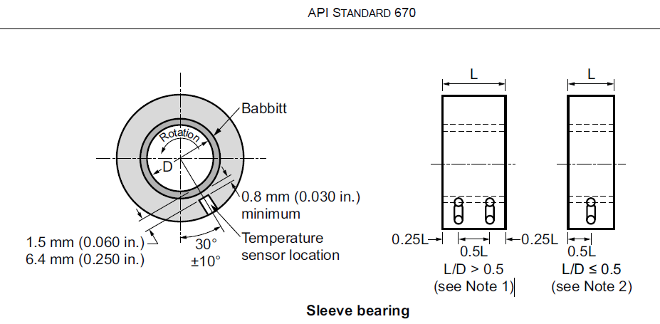
Extract from API 670 5th edition 2014
As an example, in a plantwide customer project for increasing the monitoring capability over a series of machines; most of the compressors were provided with a dedicated 3500 rack monitor, System 1 on a VM and reciprocal OPC communication to DCS.
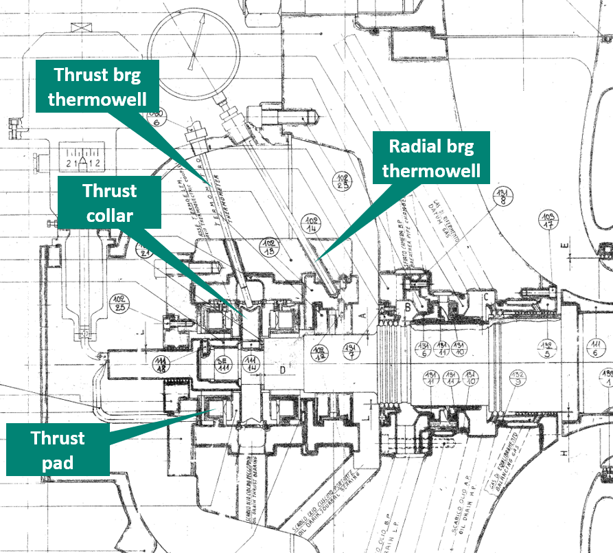
One particular and interesting case was the implementation of bearing metal temperature on the centrifugal compressor's journal bearings. This machine had temperature pickups originally built by the OEM. Using an old technique of trespassing from the outside of the end-covers to the top of the radial and thrust bearing with the use of a thermowell, then the thermocouples reached the radial and thrust bearing temperatures on the top-dead-center of the upper halves, as shown in the next sectional drawing.
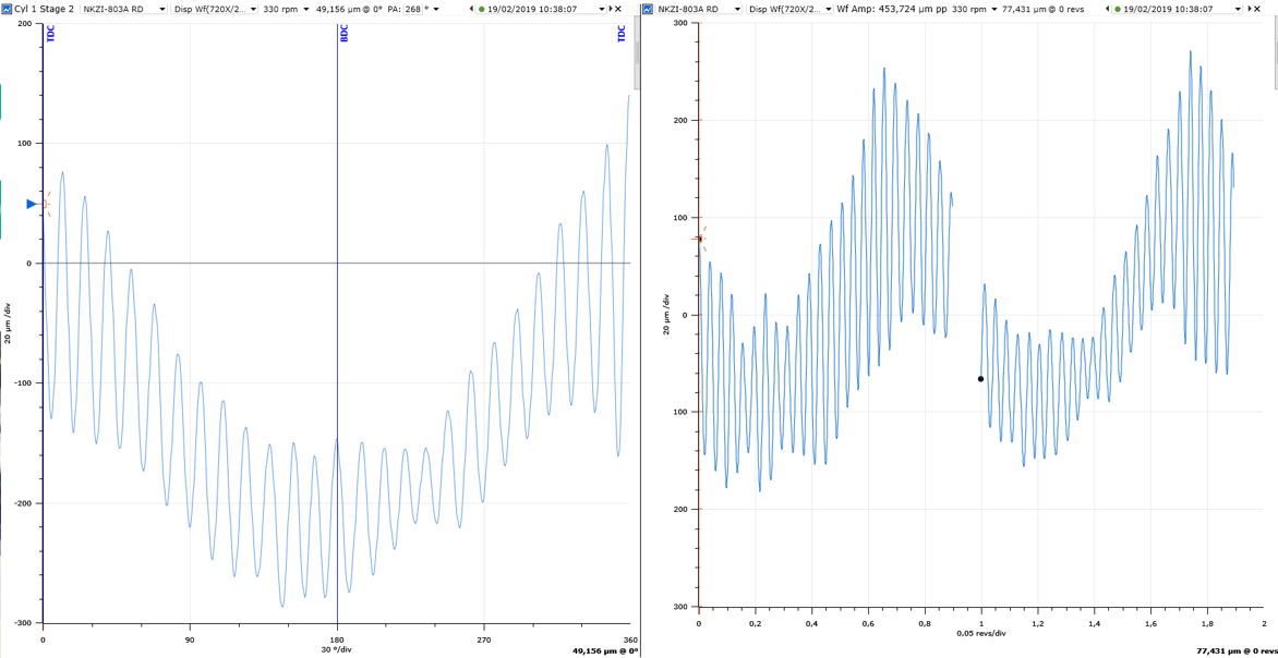
Considering OEM configuration of thermocouples, a 9.481 RPM rotor will instantly melt the protection of the babbitt (white metal) and reach the carbon steel of the journal bearing, before the hot spot temperature produced on the lower bearing half increases the temperature at the thermocouple inside of the thermowell on top of the bearing.
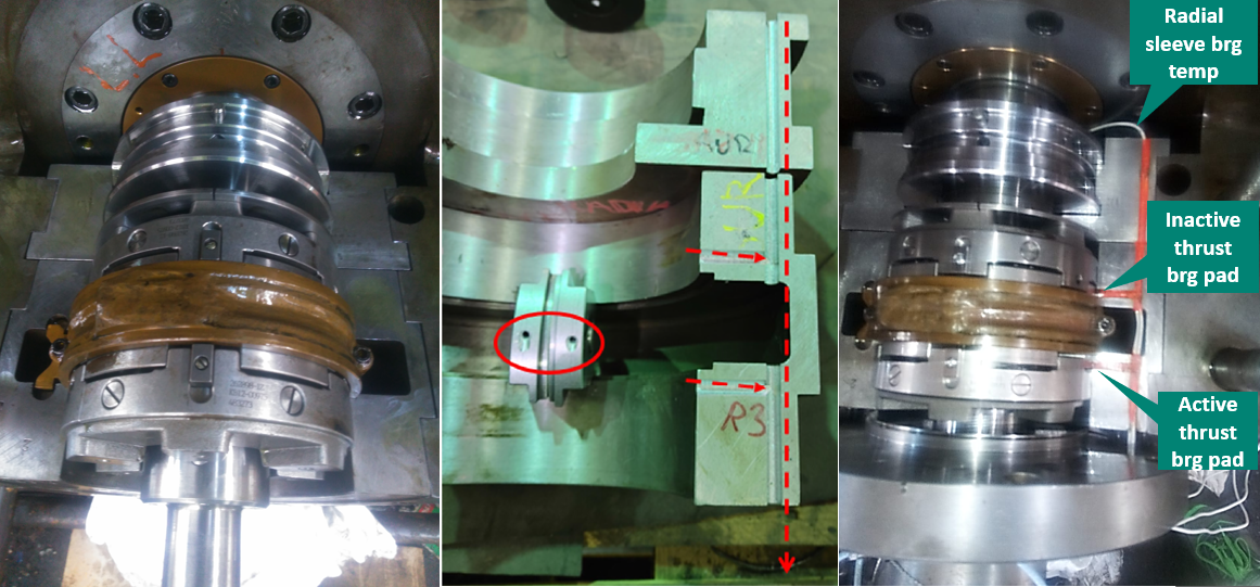
To improve the existing instrumentation, BN followed the API 670 (5th edition) recommendation and installed a double element RTD axially positioned on the lower half of radial bearing at 30 degrees opposite the oil wedge by the given rotation sense, near to the babbitted internal cylinder.
On the thrust bearing, the original temperature measuring point is on the top of thrust collar cavity, which has circulating oil, not a representative measurement of any of the contact points between the thrust collar and the axial thrust pads. So, it was agreed with the customer that the best monitoring scenario would be to place one double element RTD on a thrust pad on both, the active and inactive sides of the thrust bearing.
The machine in figure 10 demonstrates instrumentation technique common about 54 years ago. At that time, the current technical best practices knowledge and new instrumentation processes were not available on the compressor bearings. In this old instrumentation example, the original OEM design didn't consider any extra bearing provisions, so any instrument additions were limited; but afterwards easily solved by a CNC machining of new channels for the inner cabling.


Incorrectly installed sensors can cost a lot
A wrongly installed sensor can be used by insurance companies as a reason to deny any loss of profit payment.
Without proper sensor installation, the machinery monitoring system (MMS) can't fulfill its primary function of protecting and can lead to an improper diagnostic on the machine condition, leaving the operators open to a slew of production and related safety issues

In another example found during a site visit, a customer was informed about a wrongly installed Velometer connected to a protection system. This questionable signal was the result of sensor installation on the incorrect axis; therefore, the amplitude of the Velocity signal would not increase in the case of high Rod peak forces. In such a situation, the customer's machine would be non-compliant with API 618 requirement for reciprocating compressor monitoring.
Value of certainty
Bently Nevada understands that Digital Transformation starts by surveying all process critical machines such that proper instrumentation recommendations can be made to deliver the right machine data, required for advanced diagnostics and protection.
Our Design and Installation Services aim to provide peace of mind and certainty that decision makers are getting a complete view of operations by connecting any unlinked assets to the production chain and guaranteeing that the methods for acquiring meaningful data are based on tried-and-true best practices that will create lasting ROI and deliver consistent business KPIs for years to come.
Conclusion
The world is undergoing an energy transformation that demands ecological directives be met. In response to these changes, industry must change to accommodate future market forces driven by green initiatives. In this coming future, the rotating and reciprocating machinery critical to energy production will likely change their scope in the process. What remains constant however is the inevitability of machinery malfunctions and the need for various producers to anticipate these asset issues before they impact production and safety. Also unchanging in this new energy horizon is the type of machinery malfunctions.... Rubs, shaft bow, instabilities, REB failures, knocks, looseness, misalignments... same old story; even for those more ecological types of energy producing assets used in hydro and wind generation. In summary, all industrial operators whether upstream, downstream, core markets, new energies, eco-transformation, and adjacent industries see energy transformation as a challenge, but also as an opportunity. Bently Nevada is ready to meet the demands of a changing industrial world with a proven track record of customer satisfaction and best-in-class outcomes from their investment.
Our Experts

Michel Gaslonde
Global Design & Installation Services Tech Leader
BIO
Michel Gaslonde is an Industrial Designer and a Mechanical Engineer with 13 years as MDS and D&IS for Bently Nevada. He now holds the Global Design & Installation Services Tech Leader position.