

Diagnostics of Steam Turbine High Vibration from Coupling Failure
1 Introduction
This article was written by Mr. Ryu of Korean Southern Power Co., Ltd (KOSPO). KOSPO is the largest electric company in South Korea owing total 11,284 MW of power plants. All operational conditions of their plants have been monitored using Bently Nevada’s System 1† at their remote monitoring & diagnostics center. The center has cyber-secured connectivity to System 1† at 4 different sites (35x Gas turbine, 16 Steam turbine generator, plus many critical machines) through System 1† replication. Mr. Ryu is the team leader for the center and has more than twenty years of rotating machinery diagnostics experience in power generation industry.
A sudden change of the 1X vibration response of a steam turbine at steady state operating condition is assumed to be the result of damage, such as a liberated blade.
Unexpected 1X vibration response changing was monitored from a steam turbine driven boiler feedwater pump. It was not a lost blade or debris. The root cause was identified at the disc pack coupling which connects the turbine and pump. Through Bently Nevada's RK4 Rotor Kit simulation, we could understand the relationship between coupling trouble and vibration response changes.
2 Main Subject
2.1 Equipment Summary
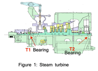
The specification and structure of the steam turbine is in Table 1 and Figure 1. This steam turbine is used to drive a boiler feedwater pump, and it controls the water flow by turbine speed.
2.2 Vibration Change
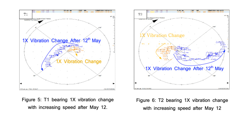
The initial sudden vibration level change was monitored at steam turbine T1 and T2 bearing (Table 2). One month later, an additional step change in vibration was observed after turbine shutdown/startup, especially evident with the 1X phase change. Table 3 shows history of 1X amplitude and phase change for 3 months. Figure 2 shows T1, T2 and Pump DE/NDE bearing direct vibration trend, T1 turbine bearing 1X vibration change is shown in Figure 3, and T2 turbine bearing 1X vibration change is shown in Figure 4.
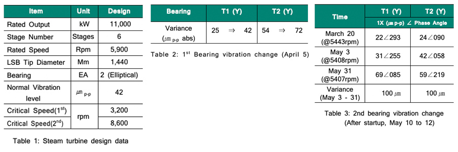
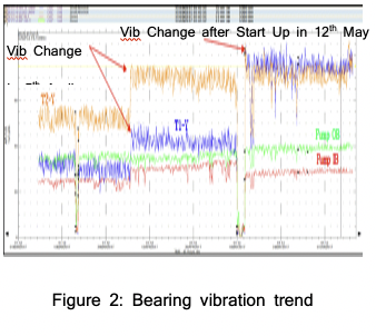
Figure 2, vibration remained relatively steady after the first increase of vibration on April 5. However, after shutdown/startup of the turbine from May 10 to 12, vibration increased significantly. It was observed that turbine side vibration level changes were higher than pump side. Finally, the 1X vector at both turbine bearings (T1 and T2) reached up to 100um pp after startup. Another interesting finding is that both T1 and T2 bearing 1X relative phase changes were out of phase. The increased 1X vibration response observed during the startup on May 12 is illustrated below (Figure 3 and 4).
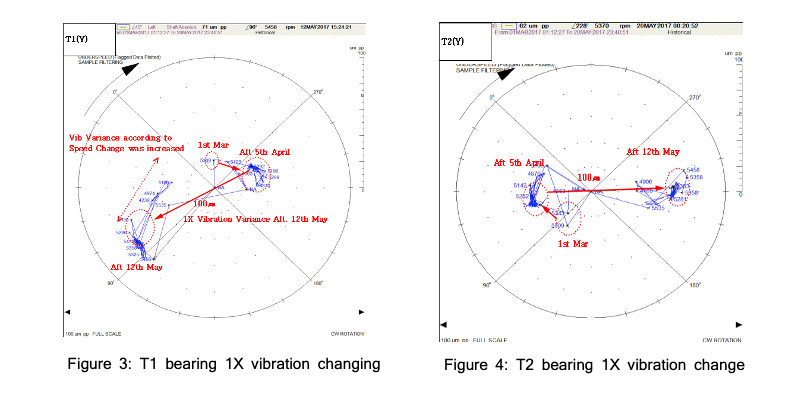
Compared with previous transient response, after the startup on May 12, both T1 and T2 bearings’ 1X vibration response became highly dependent on turbine speed. Further, the 1X vibration vectors at T1 and T2 have completely flipped by around 180 degrees each during the event.
2.3 Potential Causes of Change in Vibration
Based on the characteristics of vibration change observed, we would consider the potential cause could be. 1) Blade defect / loss of material. 2) Coupling defect. We carried out an inspection based on these two possible causes.
2.4 Simulation Test for Coupling Nut Losseness and Vibration Change
In order to simulate and investigate the relationship between the unbalance caused by looseness of the disk pack coupling (between turbine and pump) and vibration response at the turbine bearing, a Bently Nevada Rotor kit (RK-4) was used.
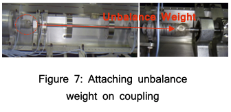
As in Figure 7, we attached 6g weight at 135 degrees on the rotor kit coupling, increased the shaft speed to 5600rpm, and compared the vibration behavior change due to the attached weight. The results confirmed that unbalance on the coupling caused an out of phase vibration response at both Rotor Kit bearings, similar to the actual steam turbine vibration change.
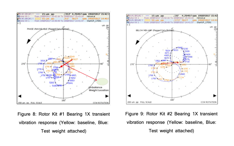
The Rotor Kit shaft vibration response at each bearing, due to attached trial weight is shown in Figure 8 and 9. The yellow line is the baseline transient vibration response, and the blue line is vibration response when weight is attached. As a result, we can surmise that, in this case, unbalance in the coupling strongly affects the 2nd resonance mode, and the phase of vibration response at this speed is also significantly changed. Therefore, it can be safely stated that the observed vibration change in the feed pump turbine is most likely caused by unbalance of the coupling.
2.5 Visual Inspection Result
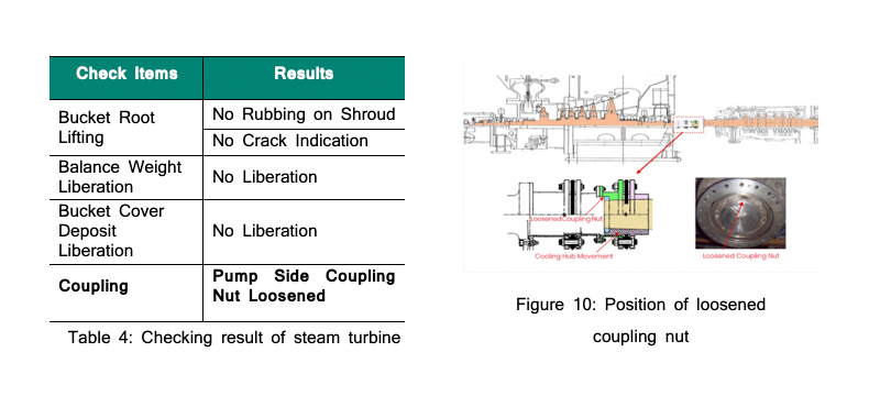
During the inspection, no crack or lost blade was found. However, looseness of pump side coupling nut was identified. The inspection result is shown in Table 4. The location of loosened coupling nut shown is in Figure 10.
2.6 Cause of Unbalance in Coupling
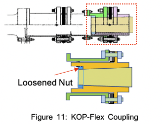
The coupling sleeve should be located to a proper depth on the tapered shaft and fastened by a nut. However, in this case it was found that the sleeve was not correctly installed, leading to looseness during operation. The loosened nut and coupling are shown in Figure 11. The loosened nut allows the coupling to move in an axial direction, eventually resulting in unbalance of the coupling assembly.
2.7 Corrective Action and Result
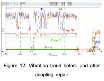
The coupling was repaired by correctly fitting the taper at the right depth per manufacturer recommendation and fastening the retaining nut to the prescribed torque. As a result, vibration was reduced to normal. The vibration trend after coupling repair is shown in Figure 12.
3 Conclusion
In a high-speed turbomachinery application where the heavy spot (unbalance location) and high spot (vibration response vector) are different, lost blade or weight was traditionally assumed as the cause of “out of phase” vibration in a small steam turbine. However, in the case of a small turbine operated above its 2nd resonance mode, we found out that unbalance of the coupling can also be the cause of this vibration change. This was determined experimentally by comparing the actual machine behavior, (including disassembly and inspection results of the turbine), with a controlled Rotor Kit simulation. It was shown that unbalance of a coupling can have a great impact on the rotor vibration behavior at the 2nd resonance mode.