

How to Set Alarm Levels and What to Do When an Alarm Triggers

Condition Monitoring Alarm Levels
Condition monitoring of rotating machinery is very much about detecting changes. Some changes are natural and acceptable, like changes due to the machine load or RPM, but most of the changes are making us wonder how long we can operate the machine safely. The most popular way to detect changes is to apply alarm levels to the vibration data that is collected. However, some do it by manually browsing through all the data that has been collected and comparing the latest readings to the ones collected earlier. Surely both ways can lead to a good or bad end result, but in today industry where resources are limited, we should be leaning more towards the use of alarm functionalities. And that is what the condition monitoring software like System1 Evo is also expecting us to do.
How to Set the Alarm Levels?
It is out of the scope of this article to define what data needs to be collected for alarming purposes. Here we assume all relevant data is collected. It may be that not all data is used for alarming, but most of it will be. We will look at some popular ways to manage the alarm settings.
Standards
There are several standards available that give guidance on what data needs to be collected and how high the alarm levels are. Some of the more popular ones are ISO, API and VDI, but there are plenty of others around.
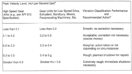
The most common approach with Standards is to use Overall (Direct) readings for evaluation and alarming purposes. Maybe the most known reading is the Vibration Severity that was defined a long time ago to be a Velocity RMS value measured over the frequency range of 10 to 1000 Hz. Today we can see that Standards provide the Overall readings for different applications in Acceleration, Velocity and Displacement, with RMS, Peak and Peak-to-Peak detection methods in use.
When we talk about condition monitoring the usefulness of Standard is very limited. The biggest issue is that they focus only on Overall readings while we collect a much richer set of data from every single sensor. Perhaps the best use of these Standards lies in Acceptance testing, and in many cases also serves the purpose of the alarm level settings on protection systems.
OEM Recommendations
Very much like standards the OEM (Original Equipment Manufacturer) recommendations are focused on Overall levels. In some case those go hand-in-hand with an applicable Standard, sometimes OEMs have slightly different levels in use. But when we talk about Condition Monitoring, the same applies here as with Standards, these measurements are good to have but are only applicable to a small part of our Condition Monitoring alarming needs.
Condition Monitoring System Providers
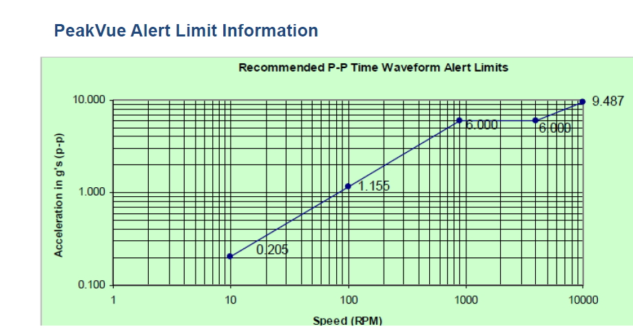
It is quite common for CM system providers to give some preliminary alarm levels for different machine types and speeds. Especially if a vendor has a unique measurement type, it is common to find some guidance about the alarm levels. For example PeakVue (technology which is also available today from Bently Nevada under the name PeakDemodulation) has been assigned the following alarm levels:
Technical Associates of Charlotte
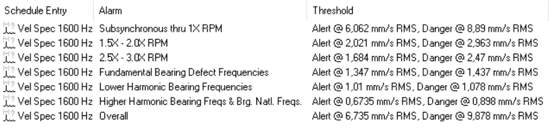
The company that is widely recognized by the fault frequency charts has also been one of the forerunners in setting spectral bands with their alarm levels for various industrial machines. Commtest and Bently Nevada have deployed TA's Best Practices and alarm levels in their condition monitoring software. Below is a screen shot showing some of the Overall and spectral band alarm levels recommended by TA, in this case for an industrial large fan with 1480 rpm.
Setting the Alarm Levels Manually
This is the most basic way of managing alarm levels and is always required function no matter what automated alarm level processing may be in use. Especially if alarm levels can be managed directly when viewing vibration data this may very functional way. When knowledge of typical readings for different machines is gained setting alarm levels roughly on right spot this way serves users well.
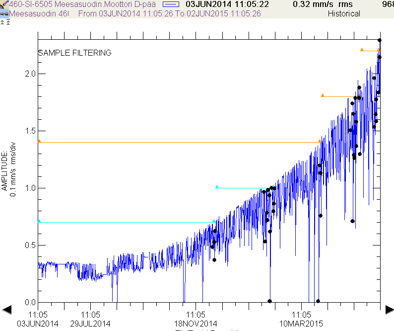
Setting the Alarm Levels - On Top of the Baseline
Already in the 1980's the condition monitoring analysis software's for portable data collector systems had an option of setting alarm levels based on the first reading. The alarm level was defined to be a certain factor on top of the baseline, for example 2.0 mm/s. Another option was to use a certain multiplier, for example 1.6 X, or a combination of both. This allowed a large number of alarm levels to be set easily and made sure that changes will be detected. Naturally this requires that machines are in good shape during the first data collection.
Setting the Alarm Levels - Based on Learning
When looking at the alarm settings based on learning there is clear separation into two different ways of thinking, either statistical or Artificial Intelligence (AI) based.
The statistical method looks at the vibration levels alone. Alarm levels are calculated using data collected over a certain time period or in the case of portable data collection over a certain number of samples. Typical formulas for alarm levels are:
Lower alarm: Mean + 3.0 X Standard Deviation
Higher alarm: 1.6 X Mean + 2.0 X Standard Deviation
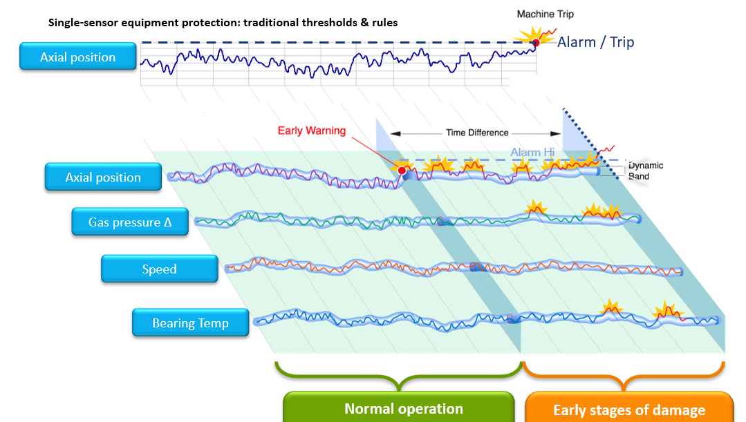
The modern AI based systems are taking more data than just vibration into consideration. By combining operational data and other condition related data it is possible to detect changes earlier before traditional vibration alarms are triggered. There are plenty of offerings in this space today, and the basic idea has been around already for a few decades.
Setting the Alarm Levels - Number of Alarm Levels
The number of alarm levels is very much dependent who is viewing the alarms. If we look at the topic from the Control room point of view, operators don't want to see any early warning, they only want to see alarms that require immediate action. Therefore condition monitoring data when viewed by control room people should only have the HH (High High or in other words Danger) alarm level, and maybe also H (High or Alarm). On the other hand, the Condition monitoring group wants to see the earliest changes in machine operation in order to give maintenance teams time to prepare for repairs (or correct the situation before a failure path actually has started). In order to fulfill the needs of both teams, S1 Evo allows users to have four alarm levels on every trend data that is collected. But typically only two or three levels are used.
Setting the Alarm Levels - How to Manage
When several users are viewing the condition monitoring data and alarms, it is important to agree who has the administrative rights to the alarm levels. Situations where multiple parties are ammending alarm levels up and down, or try to have different alarm levels on the same data, should be avoided.
What to Do When an Alarm Triggers?
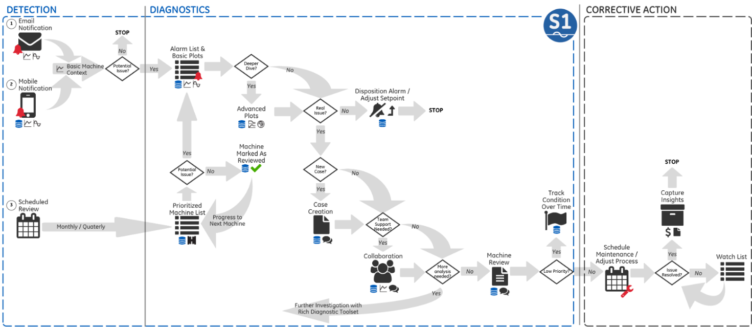
If nothing is done when an alarm is triggered, then the purpose of Condition Monitoring is very much lost. In a perfect world the necessary steps following an alarm is documented into company procedures. Here is an example what the workflow could look like:
Reaction to an Alarm - Is It Real?
It is only human to suspect that an alarm may not be real and this also applies to condition monitoring. Some possible reasons for a nuisance alarm are:
- Taking readings from a wrong measurement point (portable data collector, PDC)
- Sensor is overloaded due to rough placing on the bearing housing (PDC)
- Cable connector is loose
- Cable is broken
- Sensor is not sitting properly on the surface (PDC)
- Sensor has been removed from its mounting place (online systems)
- Surface is too hot
- Wrong sensor is used
- Sensor is faulty
- Wrong settings for the measurement
- Noise and disturbance from the environment
- Insufficient dynamic range of the sensor
- Alarm level setting is too low
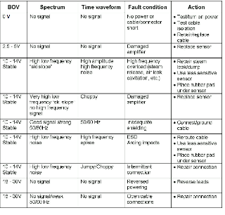
In order to decide if the alarm is nuisance or real, it is usually necessary to analyze the vibration signal, looking at only the trends is unlikely to be enough. It is also helpful to see what the sensor manufacturer says about troubleshooting the sensor. In case of the accelerometers the Bias Voltage (BOV) reading may uncover the problem, with proximity probes the gap voltage may be helpful.
Reaction to an Alarm - Alarm Log and Alarm Color Codes
Is the machine currently in an alarm or not? This should be easy to see. All available condition monitoring systems use different colors to show the alarm status of each machine/measurement point/reading. But if you see everything is green, could it be that there was an alarm but the machine has returned to normal status?
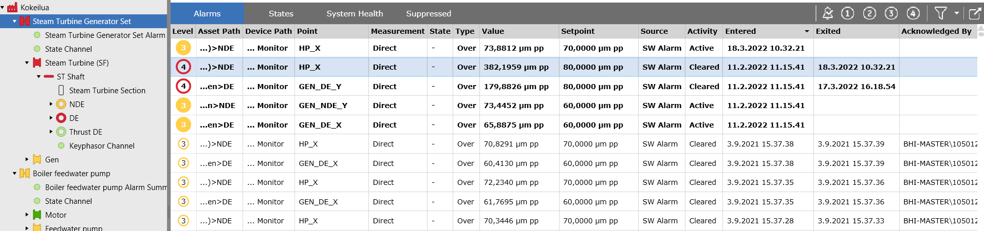
For this the Alarm Log is an important tool. Having a clear view of all alarms that have occurred, and whether they have been acknowledged, gives the user confidence that they are on top of all alarms.
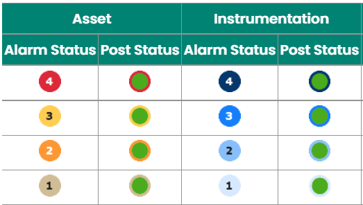
Another indication of prior alarm state can be seen in the machine and instrument hierarchy. In case an alarm is active, the alarm code is shown in full color. But in case the measurement has returned to normal and alarm is not acknowledged yet, there is an alarm code color around the green color in the hierarchy:
Reaction to an Alarm - Machine Trip
A machine trip, which is a sequence of actions to drive a machine automatically to a safe mode (usually stopping the machine), is not really part of condition monitoring but part of machine operation and safety/protection logic. One can generally say that if a machine has tripped, then the condition monitoring had failed.
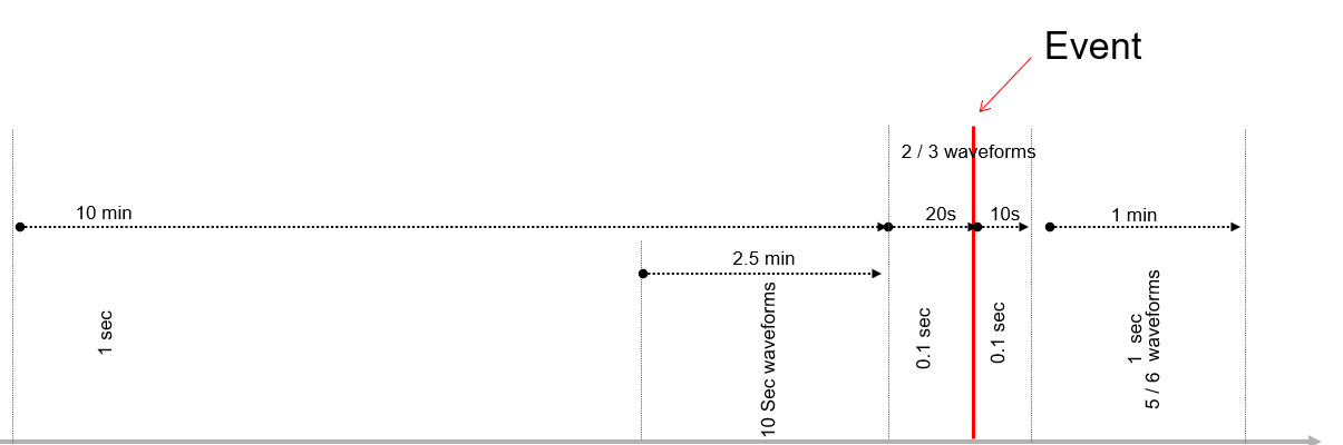
But the condition monitoring may have a very important role after a machine trip if a decision needs to be taken whether the machine can be safely restarted up or not. In other words, what was the root cause of the trip? Was it a real machinery problem, a temporary problem, an instrument related issue or just a nuisance incident? Without having sufficient data this is a guessing game. When the condition monitoring system provides rich enough data, for long enough before and after the trip, the condition monitoring team should be able to make the decision based on good engineering principles.
Reaction to an Alarm - Increasing the Alarm Level
Even though increasing an alarm level is sounding like an unprofessional thing to do, it may be an appropriate response for condition monitoring. We want to get the earliest indication, but we also want to monitor how things progress. This is especially true when multiple alarm levels are not in use. But this must go hand in hand with the root cause analysis. And after machine is back to a good condition lower alarm levels must be reverted to those previous normal values. But if multiple alarm levels are available and those are set properly, then disabling lower level alarms when those are crossed is the best practice. In this way also getting alarm levels back where they should be is easily done just by enabling all alarms again.
Reaction to an Alarm - Disabling the Alarm
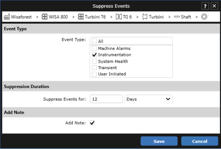
A common method of eliminating repeating alarms in control rooms is to supress the alarm functionality from a problem signal. This is not something that should be done as a standard practice, but there are times when it serves the purpose. And the same applies to condition monitoring, and with multiple alarm levels in place this is the recommended action for the lower level alarms when values are constantly trending up.
Another case is intermittent instrumentation related issue which cant be addressed until the machine is next shutdown. Or the condition monitoring system gets the alarm level from an external instrument or 3rd party system and the reading is fluctuating around alarm level. The users must not forget the disabled alarm, so the condition monitoring system needs a way to remind the user whenever logging in. It is also good practice if the alarm can be suppressed for a fixed time only, typically the estimated time until the issue will be resolved.
Reaction to an Alarm - Improving the Condition Monitoring
When a machinery malfunction has been detected but the machine cannot be shutdown for the repair immediately, the operation of the machine will have a higher risk. This risk may be managed by improving the condition monitoring activities. Some of the common ways to do this are:
- Increasing the frequency of off-line (route based) data collection.
- Installing a temporary online system on an alarming machine.
- Improving the quality of route data, like adding new measurement points and improving spectral resolution.
- Utilizing alternative condition monitoring technologies such as temperature monitoring.
- Improving the measurement cycle on an Online system.
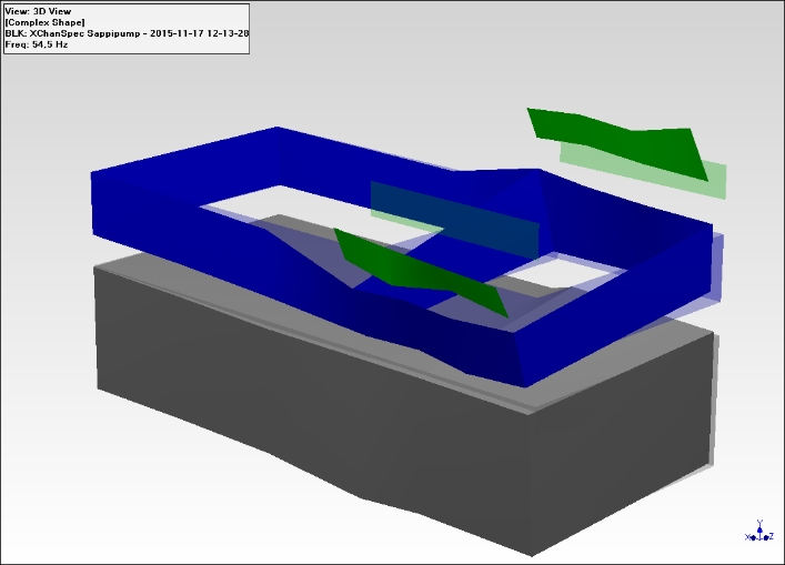
- Using special techniques to define the root cause, like operational deflection mode shape and motion amplification with a camera.
Reaction to an Alarm - Putting Less Stress on a Machine
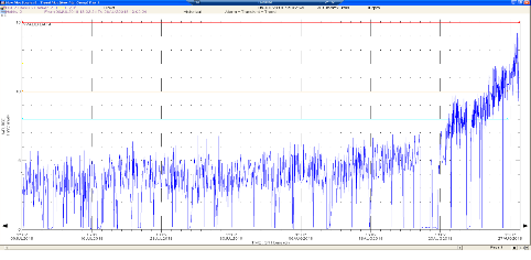
In some cases, operation of the machine can be managed by putting less stress on it until the maintenance can be performed. The most common ways to reduce load on a machine are to reduce output, and with variable speed machines lower the speed.
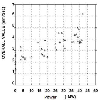
Figure 16. A Frame 6 gas turbine gearbox vibration values vs generator output
Reaction to an Alarm - Other
Some other ways to manage a machine in alarm are:
- Adding lubrication to the failing rolling element bearing.
- Adding cooling to the failing part, usually on a rolling element bearing. This can be as simple as putting a small fan blowing directly on the bearing.
One extreme example of how to react to an alarm can be found in the history of Bently Nevada. A nuclear power plant reported a vibration alarm on a reactor circulation pump. Mr Don Bently performed the root cause analysis and was convinced the pump had a cracked shaft. Since the customer did not want to shut down the pump, Mr Bently ordered all his workers to stay at least 200 miles away from the plant!
Our Experts

Petri Nohynek
Field Application Engineer
BIO
Helping manage all Your rotating machinery by suitable solutions that are correct for Your organization