

Reciprocating Pumps Condition Monitoring

Fracking process - introduction
Hydraulic fracturing, or "fracking" as it is more commonly known, is one of the methods used for unconventional extraction of oil and natural gas fields. Fracking is a proven production enhancement technology used for extracting oil, natural gas, geothermal energy, or water from deep underground.
It is the process of injecting frack fluid (mixture of water, proppant, and chemicals) at high pressure to create small fractures in the rock formations to stimulate the production and safely extract energy from an underground well after the drilling has ended and the rig and derrick are removed from the site.
The process is variable from a single frac stage in an exploratory well to 50+ frac stages in unconventional reservoir well takes. The number of frac stages, fracture design, flow rates, volumes and frac fleet size (HHP) are defined by a group of specialists and once the fracturing operation is finished, the well is considered "completed" and is now ready to safely produce. Entire set up runs in several intermittent cycles.
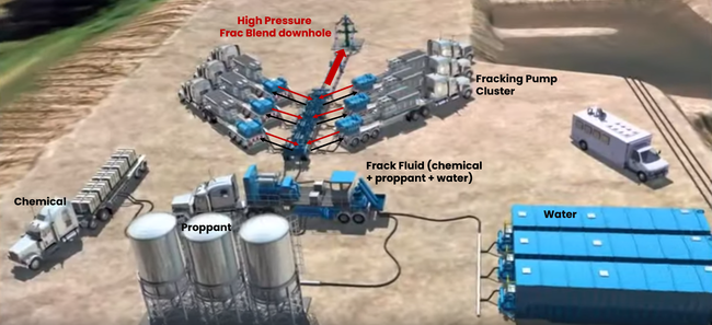
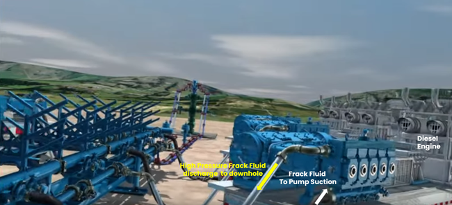
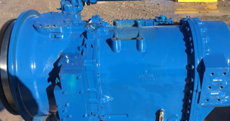
Fracking operation involves injecting frack fluid at high pressures which is established through pumps. These fracking pumps, often reciprocating pumps, are either mounted on a skid on-ground or on mobile trucks. They are driven by diesel engine through a transmission gearbox involving clutches. Piping arrangements direct the high pressure frack from individual pumps to the common header before it is injected into downhole.
Fracking process - operational challenges
These fracking pumps operate in harsh operating conditions and face many challenges for continued operation:
Health, Safety and Environment (HSE) exposure - These pumps operate at extremely high pressures typically ranging between 11000 - 13000 psi (up to 900 bar) without any online protection system. This creates a significant exposure to people, assets, and environment from a HSE aspect.
Maintenance philosophy - The high-pressure reciprocating pumps used in fracking operations typically have very limited instrumentation to support online data analysis. Major maintenance decisions are therefore driven by time rather than based on the asset's real condition. Breakdown severely affects fracking cycles, increases maintenance costs and adds up to massive inventory requirements.
Operation Excellence - Fracking pumps operate in different operation modes. Different wells mean different operations and associated challenges. Intermittent operation, not fixed allocation and limited automation in places creates many variables needed to achieve sustained productivity, efficiency, availability, and reliability.
Smart fracking solution
Bently Nevada's smart fracking instrumentation and monitoring solution is designed to address a wide range of safety and operational factors and ultimately improve operating margins. A few salient features are:
- Capture and register detailed fracking data
- Minimize risk of catastrophic equipment failures and labor accidents
- Reduce unplanned maintenance events
- Increase planned and low-cost maintenance activities, anticipating failures on rolling element bearing, transmission, power end and fluid end of pump
- Move away from time-dependent maintenance in favor of a condition-based maintenance approach (a cost-effective maintenance approach for optimal operation with minimal downtime and maintenance costs)
- Improve execution of maintenance activities
- Improve data integration, correlation, and analysis, to provide better in-depth knowledge and actionable information about equipment health
- Increase equipment availability and maximize the number of operations per day
- Increase operating efficiency
The solution can be deployed on any OEM's machine and is easy to retrofit as most sensors are case-mounted and just require simple modification of drill, tap and spot-face for installation. Bently Nevada's Smart Fracking solution was first deployed in Latin America and this article will discuss in-depth the installation and results from that installation.
Instrumentation
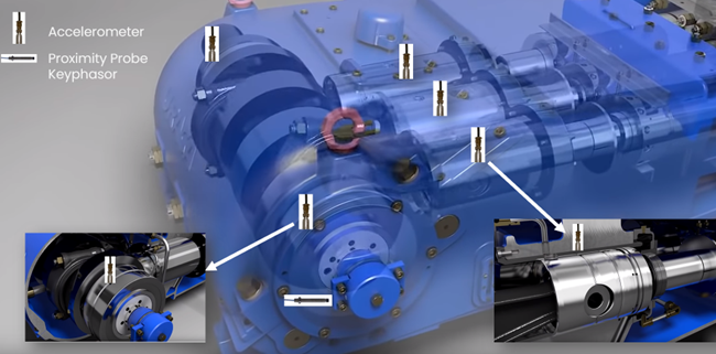
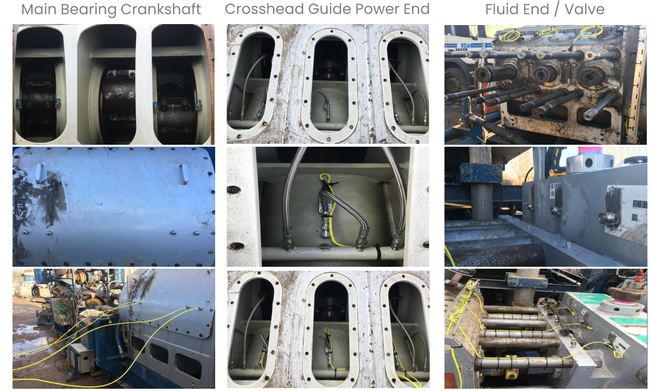
The pump is divided into three main subsystems to assess condition and avoid failures. The following are the systems and the related sensors installed on them. A triplex (3 cylinder) reciprocating pump is being considered here for explanation. Please note that based on the pump's criticality, size and intended machine health monitoring extent, the number of sensors may be optimized with most vibration-sensitive locations being monitored as a minimum.
Reciprocating pump
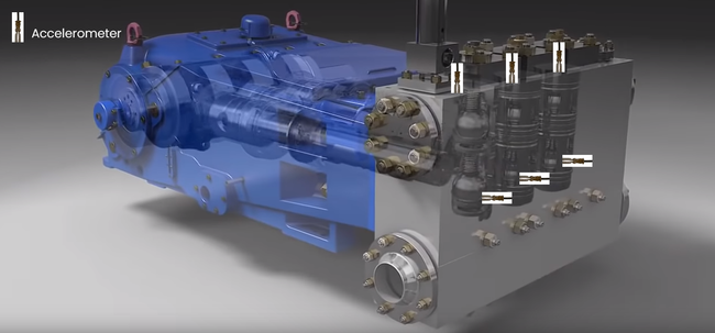
- 6x Accelerometers on fluid end [pilot installation used 3 Accelerometers on fluid end]
- 3x Accelerometers on crosshead guide - power end (1 on each crosshead guide)
- 2x Accelerometers on input power shaft bearings
- 2x Accelerometer main bearing crankshaft [pilot installation used 4 sensors]
- 1x Keyphasor (crankshaft) [the speed sensor on diesel engine can be used for fault frequencies on transmission]
Transmission gearbox (as per API 670 recommendations)
- 1x Accelerometer across high-speed shaft
- 1x Accelerometer across low-speed shaft
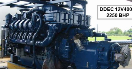
Diesel engine
1x Accelerometer on the fan bearings
1x Accelerometer on the water pump
1x Accelerometer on the power shaft main bearing
Note: Pilot installation did not monitor diesel engine
Operation data from PLC (controller) can be ingested into System 1 (via Modbus or OPC communication) wherein fracking data is correlated with machine monitoring data. Also, data from an engine control module (ECM / ECU) can be exported to System 1 (using CAN to Modbus/OPC converters). This helps in setting up state-based monitoring, alarming and analytics.
Failure modes
Using the afore-mentioned instrumentation connected to online monitoring and protection systems and to the asset health management platform System 1, the following failure modes can be detected:
Excessive crosshead clearance
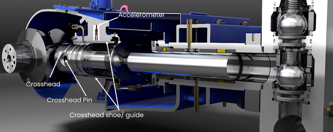
The accelerometers installed on top of each crosshead guide/slide can detect machinery problems due to impact-type events such as mechanical looseness in the running gear, excessive clearance in the wrist pin bushing and between crosshead guide and shoe.
Excessive clearance between crosshead pin and its bushing
Excessive clearance between crosshead pin and bushing will show up as two high amplitude knocks in filtered crosshead vibration waveform as the forces on crosshead pin change direction from compression to tension and vice versa.
Loose or cracked nuts/bolts, or pistons/plungers
Accelerometers installed on crosshead guides help to detect loose or cracked nuts/bolts and loose plungers (also referred as pony rod) using 3-2000Hz filtered amplitude.
Fluid end problems (valves and pressure packing failures)
To identify failures on valves and pressure packing, externally installed accelerometers on cylinder track vibrations from valve opening and closing moments, impacts and synchronisms. Crankshaft position is used to precisely locate the problem source and create a timely issued maintenance notification in case of unexpected failure and to avoid unnecessary replacements. These sensors are installed in the back of the fluid end of each cylinder, as close as possible to the valves. This positioning maintains clear access for valve replacement and fluid removal.
Trapped debris
Debris ingestion in the fluid end can be detected via crosshead and/or cylinder vibration. In case of debris in the head end (HE) chamber, the plunger will push the debris all the way until the end of stroke at top dead center (TDC) where the plunger tries to compress the debris which creates an impact at crosshead pin. This high energy filtered impact is observed between 350 - 10 deg which is near the TDC of 0 deg crank angle.
Transmission problems (gear mesh failure and bearing failure)
Two accelerometers are placed on the transmission to detect gear mesh frequencies and failures, including torque issues caused by the large distance between the transmission and pump. Our combination of software and hardware has the capability to monitor challenges like speed variation, high impact loading at the initiation of the fracking process, low-speed operations, access constraints to vibration-sensitive locations and multiple fault frequencies. To increase monitoring system capability, a patented sideband energy ratio (SER) algorithm tracks different variables, such as nX bands, demodulation, SER and waveforms amplitudes.
Engine problems (bearing failure and excessive misalignment)
Low frequency accelerometers are placed at suitable locations on the diesel engine. The combination of software and hardware enables the detection of rolling element bearing failures and/or impacts on bearings due to excessive shaft misalignment. The monitoring system tracks different variables, such as nX bands, demodulation, SER and waveforms amplitudes for enhanced diagnostics capabilities.
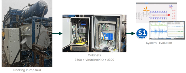
Monitoring system
Vibration transducers are connected to specialized vibration monitoring racks. In this installation, a keyphasor, crosshead accelerometer and accelerometers on the pump fluid-end were connected to Bently Nevada's 3500 Vibration Monitoring System (VMS) and configured to monitor impact events on the reciprocating pump.
Accelerometers mounted on the main bearings, transmission gearings and diesel motor were connected to a vbOnline monitoring system for specialized monitoring of forces and fault frequencies related to rolling element bearings and gear mesh forces.
Process data from the PLC was also connected to the network for fracking data correlation with machine data. This helps set up operational state-based monitoring thresholds and analytics.
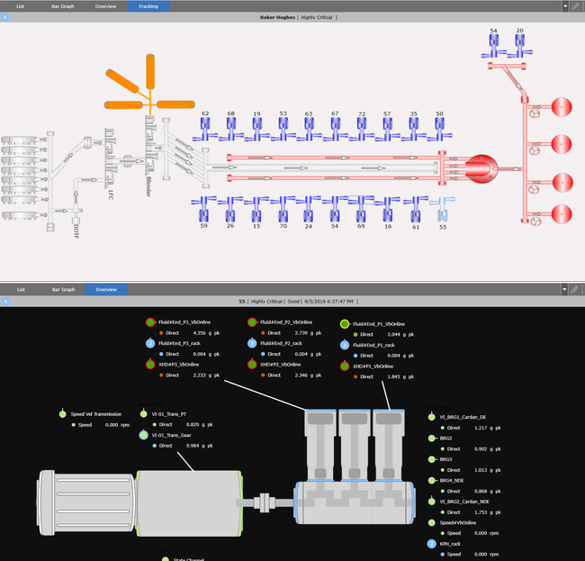
Signals from the accelerometers on the crosshead and fluid end are further analyzed in crank angle domain during each revolution on System 1 asset health management platform to identify the impacts related to events like valves opening and closing, rod reversal forces, debris ingestion and abnormal crosshead motion. Bently Nevada recommends using 0-peak subunits for impact monitoring using accelerometers for early detection of looseness.
Similarly, signals from accelerometers installed on the bearings and transmission gear are further processed into different spectral bands using the monitoring devices and System 1 software. Spectral bands are defined to identify the impacts related to rolling element bearing fault frequencies, gear mesh frequencies etc.
Condition monitoring considers two aspects:
- Identifying the baseline and further changes to the amplitudes.
- Identifying the conditions / possible failure modes related to the high impacts, increased clearances, flow related etc.
A keyphasor installed on the pump helps identifying the TDC (Top dead center) reference for each cylinder for crank angle domain analysis. Any increased clearances in the crosshead pin, crosshead slide clearances, bearing clearances, valve opening-closing timings and stiction would result in change in amplitude of impacts from baseline magnitudes. Thus, any anomaly is easily identified and can also be correlated to the specific anomalous part of the pump.
**Note: For this installation (in 2019), combination of 3500 rack (for reciprocating pump) and vbOnline (for rolling element bearing monitoring) was used. However, moving forward, a single monitoring system ‘Orbit 60' will be provided for both reciprocating application and rolling element bearing monitoring.
System architecture
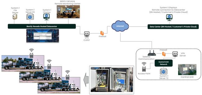
Monitoring systems (in this case, 3500 VMS and vbOnline Pro) are placed in weatherproof junction box near the pump skid. They are connected to the network through wireless modem to the on-premises System 1 (Transmit - Tx) Server. Local operation & maintenance team can access the condition monitoring data in System 1 Tx server.
Bently Nevada can further implement the replication to transmit the data from the Tx server to any cloud based or corporate data center with full cyber security compliance. Replicated System 1 (Rx) server provides the remote access capability to review the condition monitoring data anywhere using the secure connection over web so subject matter experts (SMEs) based globally can access and analyze real-time data and provide actionable insights immediately - "move data instead of moving people".
Case studies
Avoiding catastrophic failure of crosshead
Accelerometers are mounted on main power bearings, crankshaft bearings and on each crosshead guide. Additionally, a proximity probe is mounted to observe the notch on the crankshaft to obtain a keyphasor pulse for speed and crank angle reference.
An accelerometer mounted on the crosshead guide monitors high frequency vibration impacts. In case of increased clearance between crosshead pin and bushing, the magnitude of rod reversal forces will be higher and appear as impacts with increased amplitude in waveform.
Further, if there is loss of lubrication in the sliding surface between crosshead guide and shoe, it will result in wearing and increased clearances. Increased crosshead guide clearances will also result in increased impacting due to abnormal motion.
It was observed that the filtered (3Hz - 2kHz) vibration was exceeding the alert threshold level on cylinder # 3 with increased amplitude of the impact compared to baseline. Note: These pumps operate for 2-3 hours during each fracking cycle hence the lower amplitudes in the trend plot are when the pump is stopped.
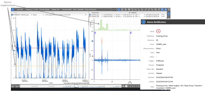
The impact was happening at a specific instant (@40 deg crank angle) during each revolution. System 1 has the capability to automatically generate alarms in different severity levels to give enough time for the maintenance team to plan the execution and secure parts availability. It can be seen in the 3D-band waterfall plot below that the severity of the impact kept increasing from 2nd August until 4th August.
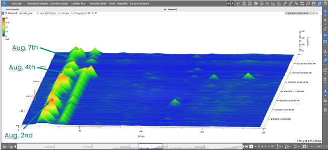
Increased vibration amplitudes at the crosshead were suspected to be due to a developed looseness condition. System 1 supported continuous operation of the pumps for an additional 2 days under close observation for any possible deterioration over time. During this time, maintenance was planned proactively which allowed for a reduction in downtime of the pump.
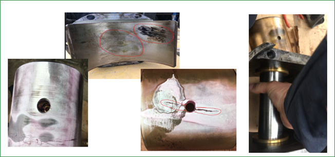
The pump was removed for maintenance and during the disassembling of the pump the failures on crosshead were confirmed. According to the Operations team, if the pump had continued to operate with the malfunction, they probably would have lost the entire pump. The pump was returned to operation after just a 2-day maintenance downtime with minimal impact to production, while saving considerable maintenance cost. As per the customer, the savings from this timely finding was around USD 300K attributed to reduced downtime and reduced repair cost.
Extending lifecycle of valves and packing
Accelerometers mounted on the fluid end monitor the valve opening and closing events. The opening and closing events are registered as impacts in the filtered waveform whereas the fluid flow during valve opening events is shown as high frequency content in unfiltered waveform. Any resistance in the valve operation, increased clearance in the valve seats or increased valve spring stiffness would show high amplitude impacts in vibration waveform while the valve is open. The frack fluid consists of a mixture of water, chemicals, and proppant; stones are avoided using strainers as they can quickly damage the internal components of the fluid end. A broadband of impacting events at higher amplitudes were observed throughout revolution as the plunger continuously stuck the stones inside cylinder. This was speculated to be stones/debris ingress into the cylinder which upon inspection was found to have eroded the suction valve's seat.
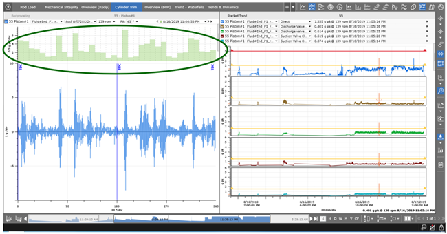
With accelerometers mounted on the fluid end, it was demonstrated that time-based maintenance could be substituted with a condition-based maintenance approach thereby extending the lifecycle of components, reducing operational risk through infant mortality detection, reducing maintenance activities, and optimizing maintenance costs.
- Valve replacement average lifecycle time was extended by 27% i.e. instead of replacing valves every 22 hours according to time-based approach, now the valves were replaced on average after every 28 hours based on condition. Outlier valves were replaced after an average of 35 hours.
- Detected valves with early failures within 15 to 17 hours and were replaced timely (instead of PM at 22 hours); hence, avoiding degradation of other components in the fluid end.
- Valve seat replacement average life cycles were extended by 50% i.e., now replaced every 60 hours (on average) as compared to earlier 40 hours. Valve seat life was extended to 66 hours, taking into consideration to replace the seats of suction and discharge valves simultaneously.
- Packing case average lifecycle was extended to 66 hours via continuous condition monitoring on the pump.
Saving pump from rapid degradation
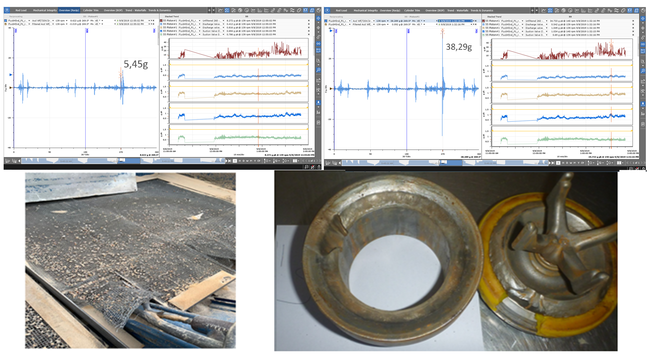
In another case, fluid end vibration increased significantly (from 5g pk to 38g pk) and the pump was shut down safely for inspection. It was determined that stones had entered the cylinder with the frac blend. This information was key for the operator so they could take appropriate action to avoid the quick degradation of valves, and valve seats and to avoid cavitation that can force the pump out of operation due to loss of suction flow against high discharge back pressure. Pump degradation was reduced by successful detection of the stones in the proppant and the fluid end lifecycle was extended by 40%. Continued operation with stones in the fluid end would have resulted in rapid failure of the whole pump.
Power transmission operation's improvement & increased lifecycle
The overall casing vibration was observed to have increased on the transmission gear when the machine was operated at 2nd gear.
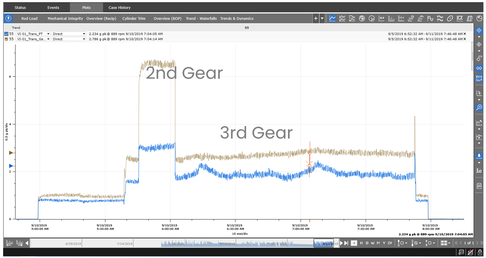
Looking at the System 1 data, operating conditions that put the transmission in distress were identified and these conditions could potentially reduce the lifecycle of the transmission. Upon evaluating with the operations team, the following operational changes were implemented based on the monitoring and diagnostics of the transmission:
- The gear change should be sequential and with some delay between the changes, avoiding impacts during speed changes.
- Initiate the sequential startup of each pump during fracking operation as it was noticed that the simultaneous startup of the pumps increased the vibration levels and load.
- Recommendation to avoid the operation in 2nd gear as the operation in 3rd gear is smoother, reducing the accelerated degradation of transmission.
Continued operation of machine on 2nd gear could have resulted in complete failure of transmission gearing with a potential estimated repair / replacement cost of USD 100K.
Conclusion
Most of the reciprocating pumps used in the Oil & Gas sector are designed as per API 674 guidelines and the standard does not explicitly provide recommendations on vibration monitoring. Historically these machines are equipped with earthquake switches which are inadequate for comprehensive monitoring and do not provide insights into changes in machine condition over time. Adopting the monitoring strategy delineated in this document, users can safely run reciprocating pumps more efficiently and with reduced maintenance costs and minimal downtime.
Condition monitoring solutions can generate enough information to detect preliminary failure modes of several components like excessive crosshead clearance, loose or cracked nuts, bolts, or pistons, excessive clearance in the crosshead pin bushing, failures in valve opening and closing, lubrication issues, trapped debris, packing failures, misalignment, gear mesh failures and anti-friction bearing failures.
Besides reducing maintenance costs by thirty percent, the smart fracking solution also minimized HSE exposure and improved efficiency through advanced alarms that enabled reliable decisions regarding machinery operation. As a result, there was an increase in the number of fracking operations per day, each one with improvement in service efficiency.
As part of the pilot, a dedicated Machinery Diagnostics Engineer was assigned to continuously look into the (static and dynamic) data and based on developing faults provide insights into machine condition so the Operations team could make informed decisions. However, having continuous remote monitoring may not always be practical due to the intermittent nature of fracking operations. Either a diagnostics engineer should accompany the fleet which may be cost-intensive or system should have autonomous diagnostic capability. Decision Support software (an extender of System 1) provides this functionality of automated diagnostics where software is constantly ingesting all machine, process, and auxiliary data; running it through pre-programmed logic blocks (called DS Analytics) or custom rules and generating alarm notifications according to severity of failure mode. Hence allowing the Operations team to focus on resolving issues rather than searching for problems i.e. optimal resource utilization. Further the HMI provision in System 1 enables dashboard capabilities whereby fleet-wide assets can be monitored more effectively.
References
- Weir Oil & Gas Hydraulic Fracturing Offering & Process Explained
(https://www.youtube.com/watch?v=YGOtFUYtCaM) - Bently_Nevada_SmartFrackingSensors_Brochure_A4-070219
Our Experts

Fayyaz Qureshi
MDS Technical Leader for RECIPs and Analytics Bently Nevada, MEIA
BIO
Fayyaz Qureshi is Senior Technical Leader for Reciprocating Compressors, Analytics and Retrofits in Middle East, India and Africa region; responsible for successful commissioning of condition monitoring and advanced analytics solutions on reciprocating machines and diagnostics.

Vinicius Alves Silva
Application Solution Architect
BIO
Started Bently Nevada as a trainee of Services in 2010, and gained expertise in products with emphasis on technologies software System 1 and Reciprocating Compressors. He is the Lead Application Solution Architect (ASA) and supports Reciprocating Compressors for Latin America.

Guilherme Silva
Industrial Sales Director
BIO
Guilherme has more than 20 years of experience in asset condition monitoring management, working with different industry segments. Guilherme earned a mechanical engineer degree by EFEI and an MBA in UFRJ COPPEAD.

Zacarias Guimaraes
Product Line Director
BIO
Zacarias Guimarães is mechanical engineer with MBA in business, has more than 20 years’ experience in Pressure Pumping working in all Americas from deepwater to unconventional reservoir and currently is the Product Line Director for Latin America.