

Accelerometers: How do they Work?

Types of accelerometers
There are numerous types of lab and industrial accelerometers, including purely mechanical devices (such as mechanical vibration switches), fiber optic, strain gage, piezoelectric, piezoresistive, capacitive, MEMS (micro-electro-mechanical systems), and others. MEMS designs, in particular, are increasing in popularity where high accuracy is not required. However, piezoelectric designs are by far the most prevalent in machinery monitoring applications and will thus be the focus in part 1 of this 3-part series. Part 2 will run in the September issue of Orbit and will examine selection criteria for seismic sensors (accelerometers and velocity sensors). We’ll wrap up the series with part 3 in the December issue of Orbit with an examination of MEMS technology and where it fits in the spectrum of condition monitoring solutions for less-critical assets.
Principle of operation: the simple version
A piezoelectric1 accelerometer is a profoundly simple device at its fundamental level: when you stress2 the material inside by applying force, a change in electrical charge is produced, and this change is proportional to the amount of force.
1 The piezoelectric effect was discovered in 1880 by Pierre and Jacques Curie. Initially called “pyroelectricity”, the name “piezoelectricity” was proposed by W.G. Hankel based on the Greek word πιεζειν [piezein] which means to squeeze or press.
2 This stress can be in the form of compression, tension, or shear (twist) forces.
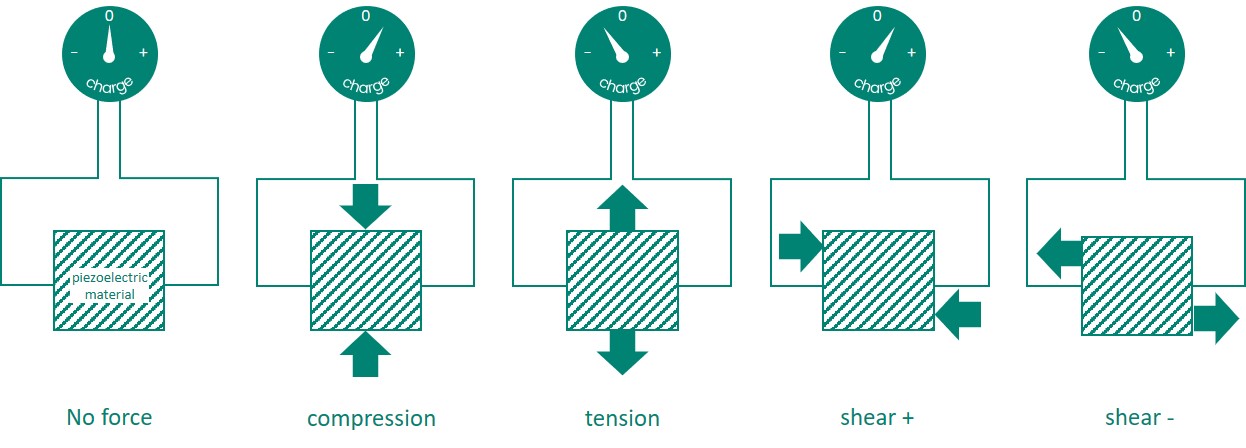
A material exhibiting the piezoelectric effect will experience a change in electrical charge when stress (force) is applied, whether compression, tension, or shear.
From high school physics and Newton’s Second Law of motion, we know that acceleration and force are related to one another by the familiar equation F = MA where
F = Force (in Newtons)
M = mass (in kilograms)
A = acceleration (in m/sec2)
It is precisely because of this relationship between force and acceleration that we can take what is fundamentally a force-detecting sensor and use it to measure acceleration; they are directly proportional to one another in systems where the mass is unchanging.
Analogous comments can be made regarding piezoresistive and capacitive accelerometers; instead of a proportional change in electrical charge based on force, they experience a proportional change in electrical resistance or capacitance, respectively.
What are they made of?
The material inside a piezoelectric accelerometer varies from crystals (natural and synthetic), to ceramics, to polymers, but have one thing in common: they all exhibit the piezoelectric effect. In other words, they respond to force (stress) with a proportional change in electric charge.
In general, crystals (quartz is the most commonly used) exhibit a smaller piezoelectric effect than ceramics. However, the piezoelectric properties of ceramics can degrade over time while those of crystals are more stable.
In contrast, ceramics such as PZT3 exhibit stronger piezoelectric properties, requiring less amplification and resulting in superior signal-to-noise ratios (SNR). PZT can also be artificially aged to help reduce the degradation that occurs with natural aging. The industry has thus largely moved toward ceramics, allowing smaller signal levels to be accurately measured and lower noise floors to be achieved.
3 Lead Zirconate Titinate
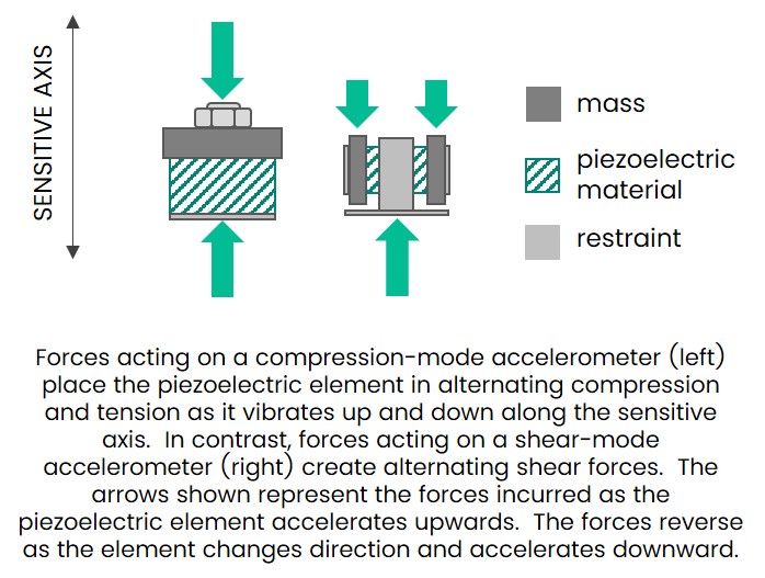
In addition to the move toward ceramic materials rather than crystals, the industry has also moved toward shear-mode designs rather than compression-mode designs. Early accelerometers used compression-mode designs largely because they were easier to manufacture. However, as manufacturing technology has progressed, shear-mode designs have moved to the forefront because they have numerous advantages:
- They produce a stronger electrical output for a given force (better SNR)
- They are less sensitive to thermal transients and mechanical preloads such as base strain
- Less prone to so-called “ski slope” effect
How are they constructed?
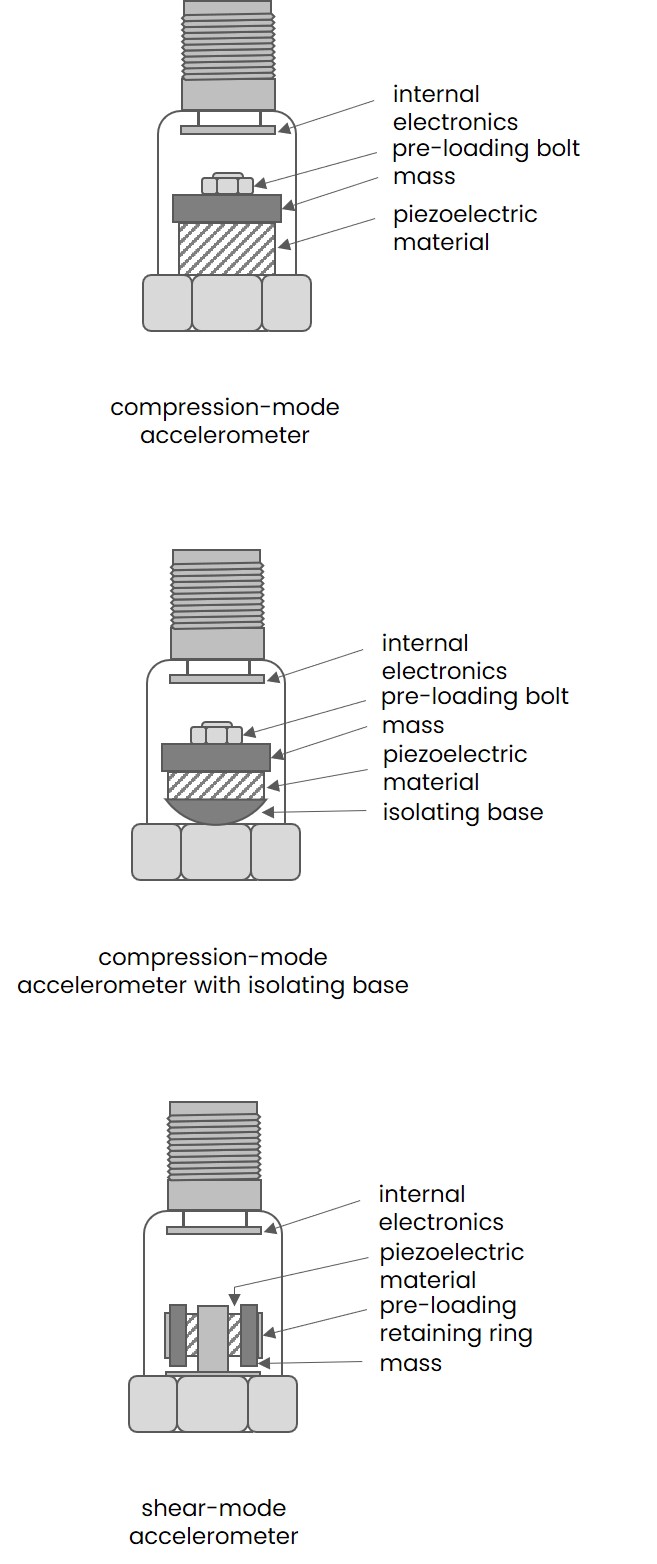
Compression-mode designs, as mentioned previously, are the simplest to manufacture. So-called “single ended” designs are the most susceptible to base strain because the piezoelectric element (PE) is connected directly to the base of the accelerometer housing. Consequently, any distortion in the mounting surface transfers directly to the PE and manifests as false vibration. Surface preparation is extremely important as a result.
Isolated compression-mode designs compensate for this by using various means of isolation including special washers and by reducing the amount of surface area between the PE and the base.
Shear-mode designs have increased in popularity as noted previously because they offer advantages relevant to machinery vibration measurements – particularly rolling element bearing monitoring where the ability to resolve small signal amplitudes is important.
Charge mode designs
As noted earlier, the fundamental operating principle of a piezoelectric accelerometer is a change in electric charge in response to acceleration (force). Thus, the native output is a proportional charge (such as 50pC/g) – not a proportional voltage (such as 100mV/g).
Before the accelerometer can be used as an input to a monitoring system, the charge must be converted to a voltage. This can be done either through the use of an external device (usually called a charge amplifier4) or via integral electronics inside the accelerometer housing. A natural question that arises is why one would ever use an external charge amplifier when the charge conversion can be accomplished internal to the accelerometer itself. The reason is temperature. While the electronics in a charge amplifier can be made relatively insensitive to changes in temperature up to about 300° F (~150 C), beyond that the output is influenced too heavily by temperature, nor can the electronics used in charge conversion survive such temperatures. To avoid these problems, when accelerometers will be mounted on machines with very high surface temperatures – such as gas turbines – it is customary to separate the accelerometer itself from the charge amplifier. This allows the charge amplifier to be located in an environment that is at a lower temperature (usually below 300° F) while the sensing element itself can tolerate much higher temperatures.
4 Other signal conditioning electronics will also be included in this device other than just charge conversion. For example, filtering and integration may accompany the charge conversion. For this reason, the charge amplifier may be sometimes called a signal conditioner or just “electronics”.
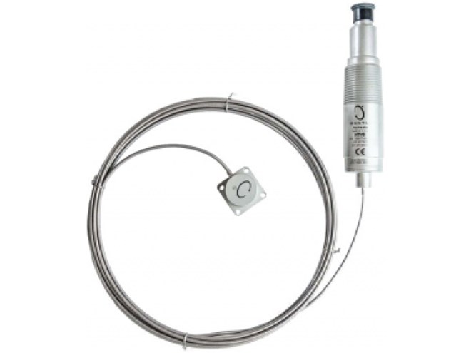
For example, the Bently Nevada 330900 High-Temperature Velocity and Acceleration Sensor (HTVAS) allows the sensing element to be mounted on surfaces up to 900° F (482 C) while the separate charge amplifier is limited to 257° F (125 C). The sensing element and the charge amplifier is linked by mineral insulated, hardline cable that is also rated to 900° F (482 C). As another example, the Bently Nevada 350501 charge amplifier can sustain temperatures of only up to 158 F, but the sensing elements to which it connects (such as Bently Nevada part number 45357-01) can sustain temperatures of up to 750° F (398 C).
The Bently Nevada 330750 High Temperature Velocity Sensor (HTVS) is an example of an accelerometer that uses a separate charge amplifier to allow use in very high temperature applications. The charge amplifier also integrates the native acceleration output to velocity and is thus called a signal conditioner. Integral cable lengths of up to 8m can be used to separate the sensing element from the signal conditioner, ensuring the signal conditioner is well-removed from the temperatures incurred by the sensing element (often the surface of an aeroderivative gas turbine).
Integral designs
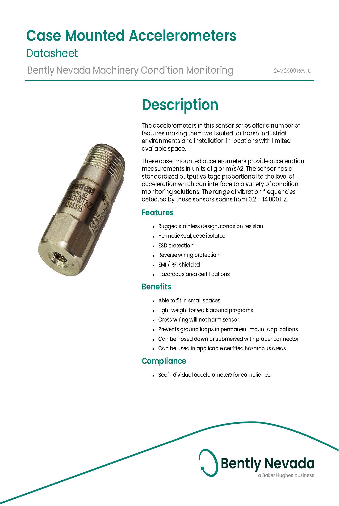
With exception of high-temperature applications as noted in the previous section, it is far more common to encounter accelerometers for industrial vibration monitoring that have the charge amplifier integrated with the sensing element. Examples include the Bently Nevada 330400, 330525, 330500, 330525, 200350, 200355, 330700, AM3100T2-Z2, and numerous others. These devices give a native output sensitivity in volts such as 100mV/g or 100mV/in/sec for self-integrating accelerometers with a velocity output.
Early Bently Nevada accelerometers dating back to the 1980s such as the 23732 had integral charge conversion, but used an external interface module that amplified the raw accelerometer signal from 25mV/g to an industry-standard 100mV/g while allowing the use of -24Vdc to power the system so that the same excitation could be used for acceleration systems as for proximity probe systems. As the years passed, our accelerometer designs improved, the need for external interface modules disappeared, and we introduced the 330400 and 330425 models to be backwards compatible with monitors using the older 23732 and similar sensors. However, because the older interface modules used three wires (power, signal, common), our 330400 and 330425 accelerometers also used three wires.
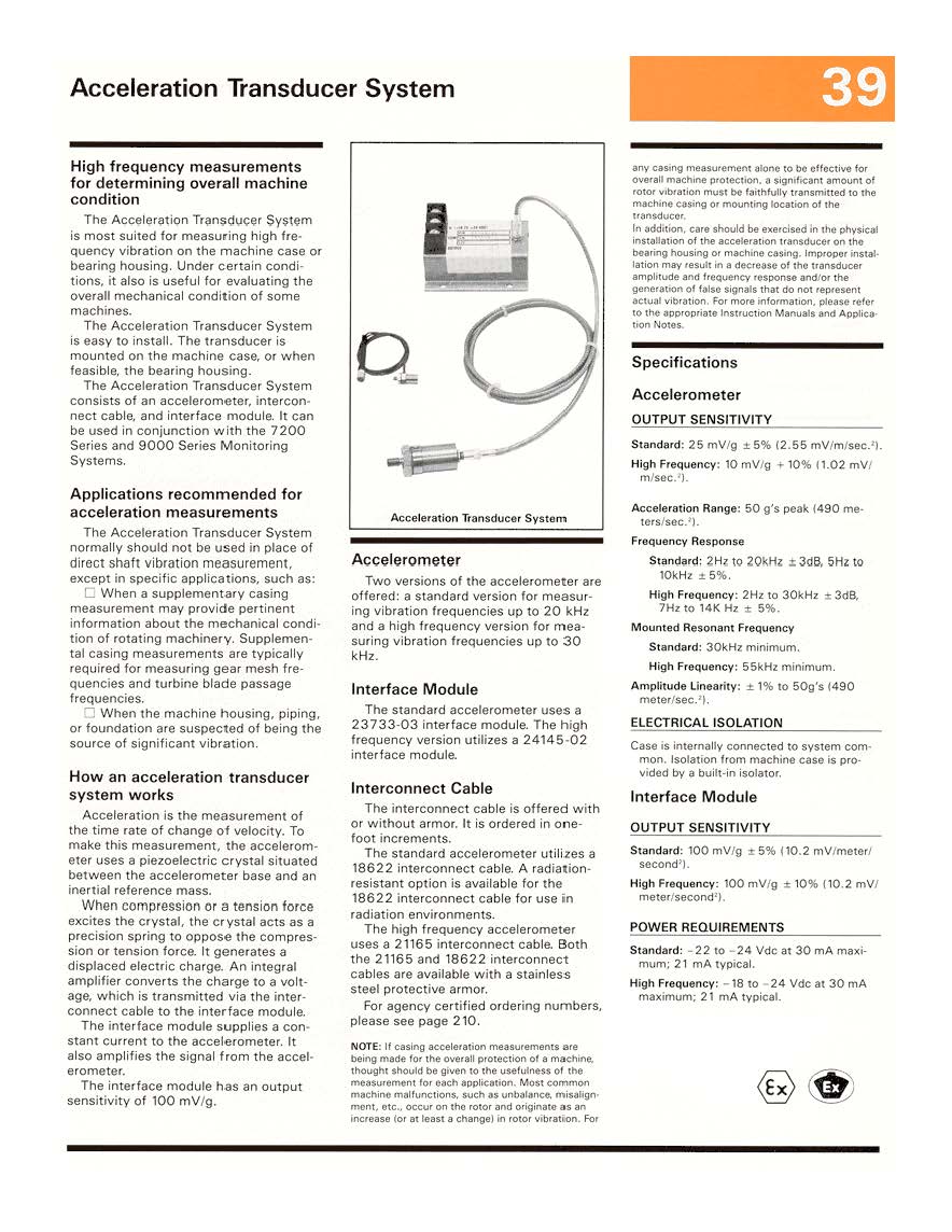
Early Bently Nevada accelerometer systems such as the 23732 used a separate interface module and had a 3-wire design (PWR, SIG, COM). Because the accelerometer had a high-impedance output, special low-noise coaxial cable had to be used between the sensor and its interface module. The 330400 and 330425 were developed as replacements for these older systems and do not require external interface modules or special coaxial cable. They retain a 3-wire design and are electrically identical to these older systems. This allows the older 3-wire transducers with separate interface modules to be upgraded without changing the monitoring system.
IEPE accelerometers
With the introduction of the IEPE (Integral Electronics Piezo-Electric) standard for accelerometers, 2-wire designs have become ubiquitous and enjoy numerous advantages:
- Run on standard, readily available +24Vdc instrument power and use constant-current excitation (usually 3mA)
- Can drive long cable lengths without need of special low-noise coaxial or other cable
- Can use standard, shielded 2-wire cable rather than 3-wire cable
- Have a low output impedance
- Are readily interchangeable with many instruments and monitors supporting IEPE-type inputs
Most Bently Nevada monitoring systems including our new Orbit 60 platform support IEPE accelerometers, charge mode accelerometers using external charge amplifiers, and our own legacy and current 3-wire accelerometer systems for maximum flexibility and choice.
IEPE accelerometers are very popular and supported in numerous Bently Nevada monitoring platforms.
Future installments
We hope this basic introduction to accelerometers has proven helpful. As we continue this series of articles on accelerometers with Part 2 in our September issue, we’ll address the question of why accelerometers are not used for every vibration application even though we can obtain both velocity and displacement readings from acceleration through single- and double-integration. We’ll also examine the applications where self-integrating accelerometers (so-called “piezo velocity” sensors) should be used versus older moving-coil velocity sensors and whether a legitimate place for moving-coil devices remains or not (spoiler alert: yes, it does). We’ll wrap up the series in our December issue with Part 3 by looking into the emergence of MEMS-type designs, their pros and cons, and the places that they can be successfully applied as part of a modern condition monitoring strategy.
Our Experts

Chris McMillen
Senior Product Manager
BIO
Chris is the Senior Product Line Manager for Bently Nevada sensors. He is responsible for new developments and lifecycle management within the Bently Nevada sensor portfolio for both wired and wireless solutions.