

Vibration issue on Compressor in a Nitric Acid Plant

This case describes how the remote diagnostic team resolved a vibration related issue on the NAP2 PAC Primary Air Compressor. This case highlights how a suitably instrumented compressor train connected to a diagnostic platform (S1 Evo) provided critical information (data) to the Bently Nevada diagnostic engineers, enabling a thorough into investigation into the vibration related issue, as well as determining the root cause. Thereafter, pertinent recommendations in relation to corrective maintenance actions were provided to both the end user and the OEM which assisted their mechanical investigations.
The clients site consists of 3 nitric acid plants along with one ammonia plant for the manufacture of various explosive products, primarily supplied to the Australian mining industry.
The NAP2 PAC (Primary Air Compressor) is one of two critical compressor trains within Nitric Acid Plant No.2 and is equipped with an online vibration monitoring & protection system with online diagnostic software.
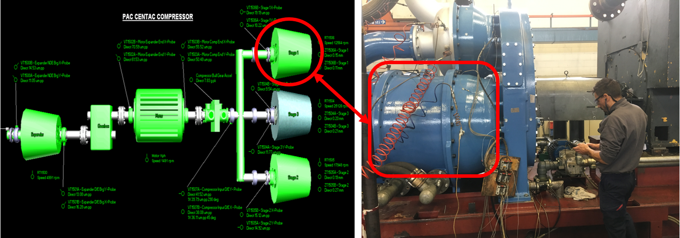
The NAP2 PAC consist of a 50 Hz 4-pole, sleeved bearing supported, 2.6 MW electric motor driving from one end a step-up gearbox, which is coupled to a hot gas expander, fitted with tilting pad bearings, via a gear type coupling. The remaining end of the motor drives a three-stage integral gear compressor (12,553, 17,934 and 25,174 rpm) via a gear flex coupling.
The NAP2 PAC was completely overhauled in March/April 2019 during a scheduled turn-around period, conducted once every 5 years, inclusive of a motor rotor replacement, step-up gearbox overhaul, a new air end compressor installation as well as hot gas expander thrust bearing and thrust collar replacements/repairs. Additionally, the expander seals were replaced with like-for-like but tighter clearance carbon seals, the entire drive train was re-aligned, and a new anti-surge valve was installed.
During bi-monthly remote diagnostics review as part of an SSA agreement (6 times annual remote diagnostic reviews of all steady state and transient vibration data), it was verified that the NAP2 PAC would occasionally trip off-line due to high compressor 1st stage vibration (dominantly due to the 1X component) during steady state operation. Diagnosis verified compressor 1st stage rub (trip) events during steady state operation as well as stall/surge related issues during shutdowns. Additionally, a prominent 1st stage 3X vibration component manifested post the turn-around with increasing amplitudes up until the OEM attended site to perform a repair in (February 2020). It is interestingly noticed that the 3X vibration occurred only at reverse component, not at all at forward component, when viewed at full-spectrum cascade or waterfall plots.
Problem statements:
- The NAP2 PAC is a critical machine on site that is responsible for overall manufacturing process.
- The NAP2 PAC drive train was completely overhauled during a once-every-five-years turn-around period including the installation of a completely new air compressor.
- Shortly after the turn-around re-start plus due to a process related issue, the compressor was shut down with a significant 1st stage surge event recorded.
- During the subsequent re-start, the compressor tripped due to high direct (mainly 1x synchronous) vibration measured at the compressor 1st stage associated with a rub condition.
- Thereafter the NAP2 PAC experienced several additional 1st stage rubs during steady state operation as well as 1st stage stall/surge issues during shutdowns.
- Additionally, a prominent 1st stage -3x reverse vibration component post the turn-around further increased vibration level, which brought the OEM to site to repair the machine
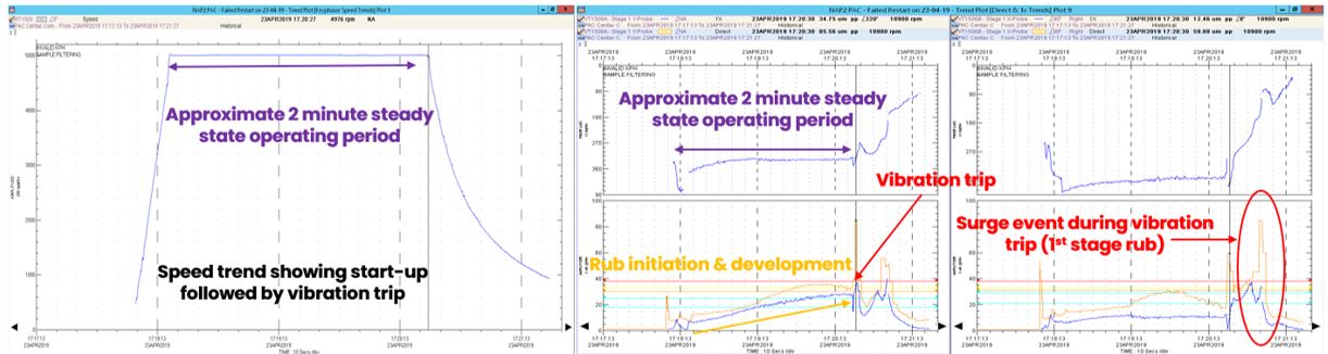
On April 23rd, 2019 the NAP2 plant was shut down due to a plant process related issue. The plant operators then attempted an immediate restart. Approximately two minutes post the re-start @ 17:20:27 the OEM Danger (Severity 4) trip set-point was breached and the unit tripped off-line on high 1st stage direct vibration. Review of the trip data indicated a 1st stage rub had initiated the vibration related trip. During the shutdown vibration related trip event, the compressor 1st stage experienced rotating stall/surge related issues at approx. 11,350 rpm and between approx. 5,600 & 4,300 rpm (See Figure 2). These stall/surge related issues associated with the anti-surge system (inlet guide vane IGV and timing/control related issues). See figure 2 over-leaf.
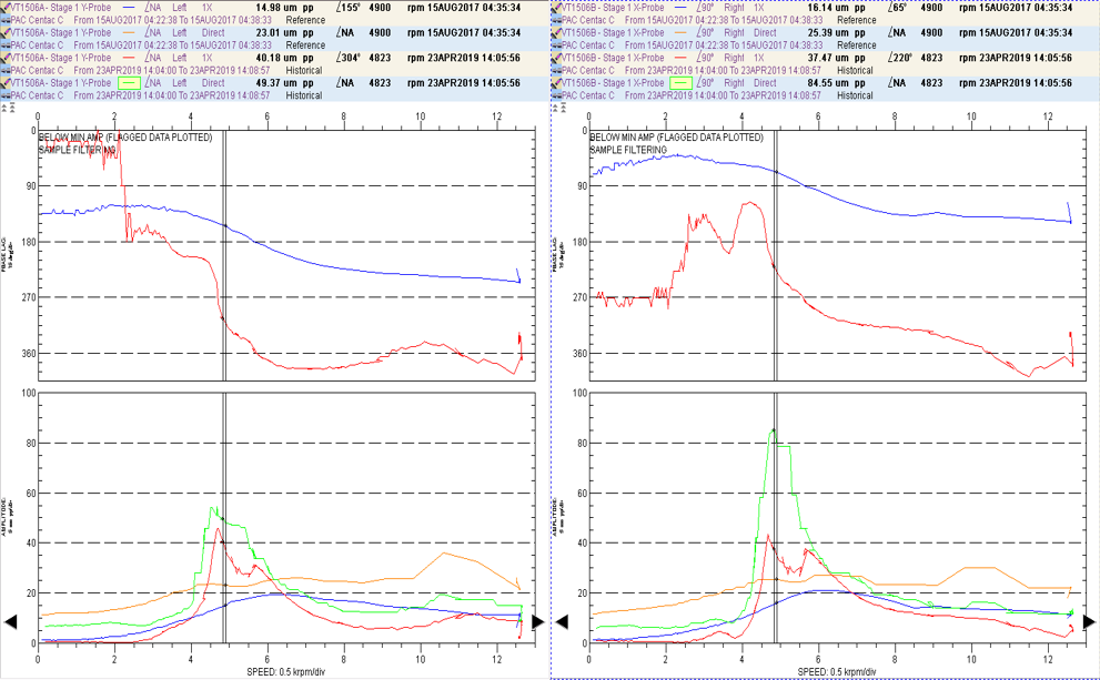
The direct/1x synchronous trends and direct orbit/timebase plots indicate the significant sub-synchronous (0.53x) vibration associated with compressor 1st stage stall/surge issues during the April 23rd, 2019 shutdown. Compressor 1st stage Bode plots show increased not-1x vibration (GREEN line) during the April 23rd, 2019 shutdown transient event (BLUE & ORANGE lines are 2017 reference data), as shown in Figure 3.
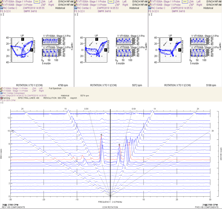
The significant compressor 1st stage sub-synchronous vibration (35 µm pp @ -0.53x & 21 µm pp @ 0.53x @ 2,700 rpm) measured during the April 23rd, 2019 shutdown (vibration trip) transient event is demonstrated in the full spectrum asynchronous cascade plots as shown in Figure 4.
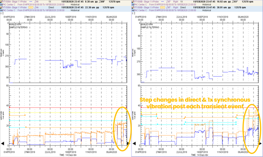
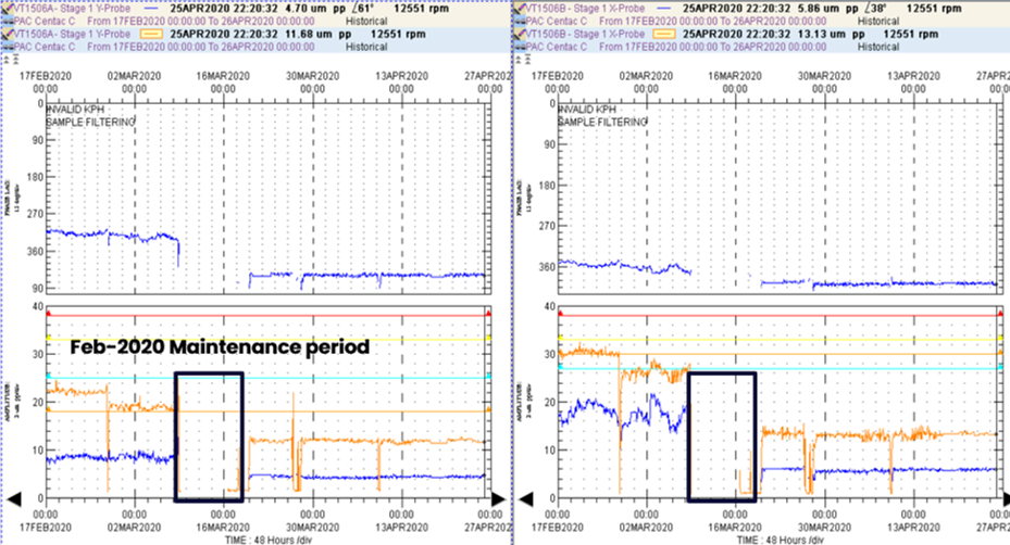
The compressor 1st stage direct & 1x synchronous long-term trend plots verify a series of step changes in direct values post each shutdown transient event associated with increasing -3X reverse component vibration with amplitudes as high as 14 um pp measured on February 6th, 2020. 1X synchronous trended values were also noted as being variable post each shutdown transient event as well as during steady state operation.
Direct values became highly variable in January 2020 breaching the OEM Alert value of 33 um pp, but remaining marginally below the Danger (trip) set-point of 38 um pp.
Runout signature analysis was well described as shown in [1] in the Orbit For the periodicity of such irregularities observed by the XY proximity probes, different combinations of forward and revere components are observed. The rules for such an analysis are summarized below in Table 1.
Table 1 - Runout signature patterns as indicated by forward and reverse nX components
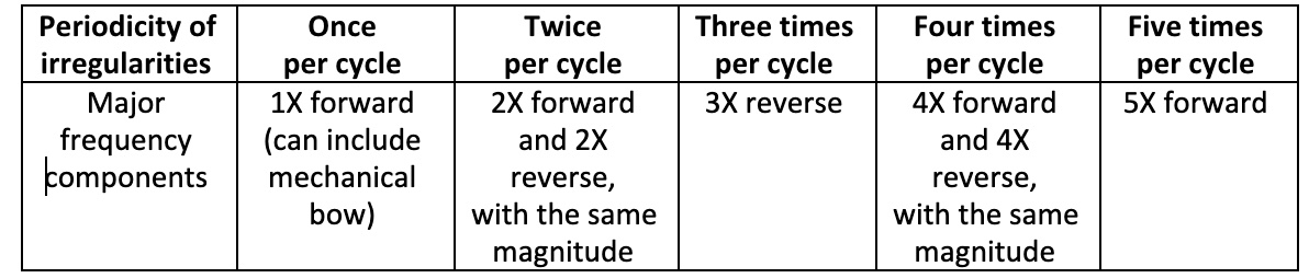
The constant amplitude -3X reverse component vibration measured throughout the entire speed range during each of the NAP2 PAC shutdown transient event specifically relates to run-out measured at the probe-tracking region of the 1st stage journal, rather than a rotor dynamic issue. However, the increasing 1st stage run-out (increasing -3X reverse precession component amplitudes post each shutdown transient event) was an indication of a defect progression specifically associated with the impeller to journal fit. It should be noted that there is no 3x forward vibration at all.
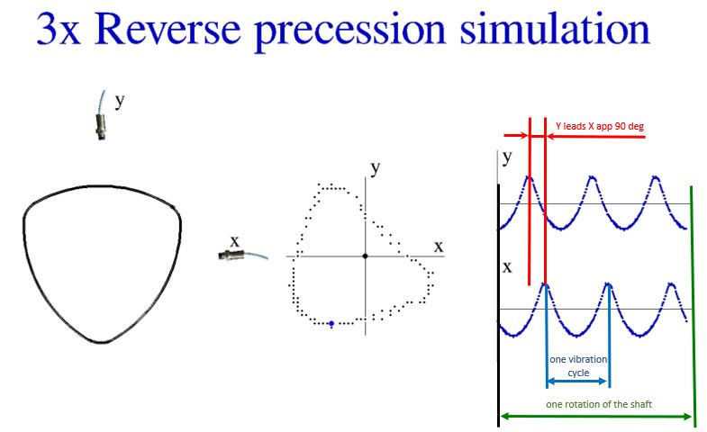
To visualize this phenomenon the animation - Run-out simulator was created using Python Programming Language. The predefined object is rotating around the geometrical center and distances from orthogonally mounted X and Y proximity probes are recording. The orbit plot can be built based on the X and Y waveforms recorded.
The polygon (journal) direction of rotation is CCW, at the same time the direction of the XY waveforms based orbit precession is CW. There is clear evidence of -3X reverse precession component presence - the direction of the shaft rotation is from X to Y probe, with the Y probe waveform is leading by 90 degrees, as shown in Figure 6.
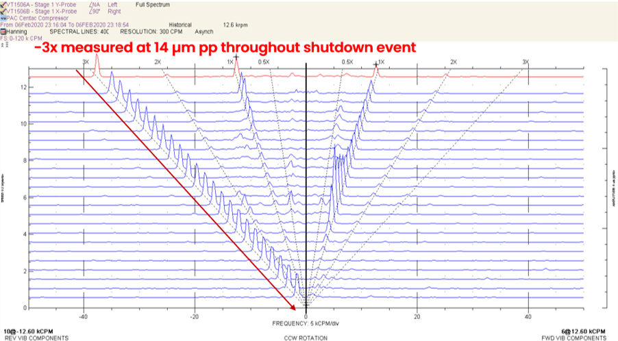
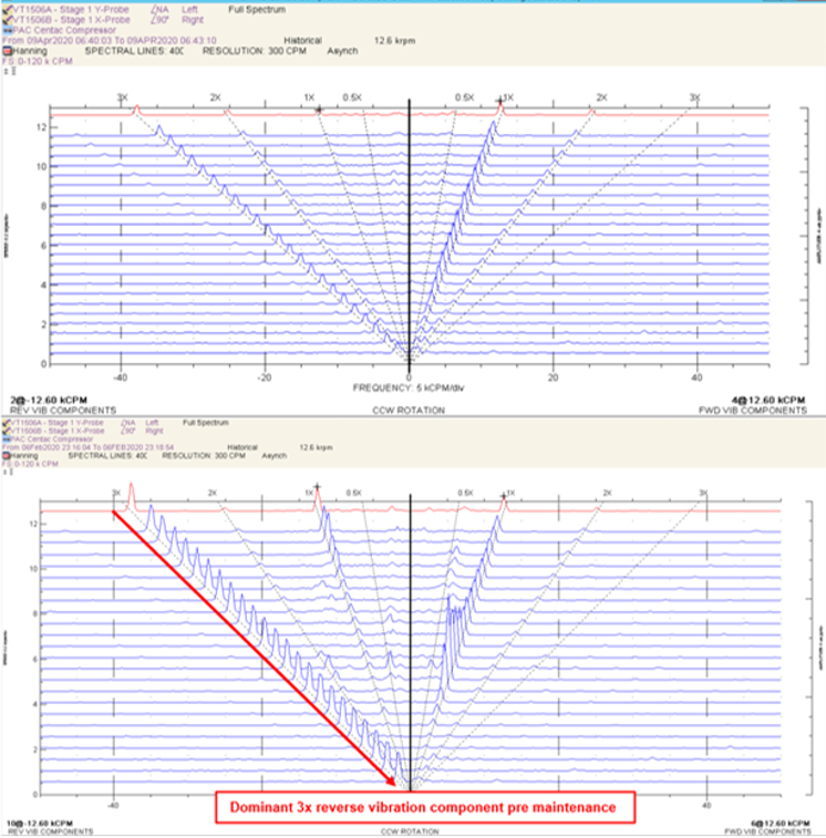
The February 6th, 2020 shutdown was the last shutdown transient event prior to the OEM site-based repair at the end of that month. The Compressor 1st stage full spectrum cascade plot indicates -3X reverse component vibration measured in the region of 14 um pp throughout the Feb 6th, 2020 shutdown. 1x synchronous reverse vibration amplitudes are also higher than the forward components, the exception being as the rotor transitioned the 1st (translational) critical speed range.
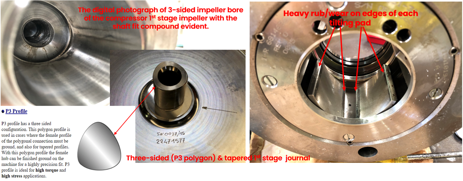
The -3X reverse component indicated a compromised fit between the impeller bore and the rotor journal (tapered polygon P3 design) resulting in journal deflection during steady state and transient operation, as shown in Figure 7.
Bently Nevada was informed of the following site-based maintenance findings (Mid-February 2020), as shown in Figure 8 and subsequent repair work:
- 1st stage tilting pad bearing indicated signs of heavy rub on the bottom two pad edges.
- 1st stage cylindrical bearing indicated signs of rub at the top of the bearing and heavier at one end.
- 1st stage impeller bore indicated evidence of anti-cease/slip compound used during the impeller installation at the OEM factory in Italy.
- 1st stage tilting pad bearing replaced.
- 1st stage cylindrical (outboard) bearing replaced.
- 1st stage impeller was slow-speed balanced (dedicated shop balancing machine - in a low-speed balancing machine).
The shop balanced original impeller was re-installed onto the 1st stage rotor journal as per OEM specifications with no anti-seize/slip compound applied.
Thereafter, compressor 1st stage direct & 1x synchronous vibration has remained steady up to the presentation compilation date (January 30th, 2022) with no compressor 1st stage stall/surge, rub events or increasing -3x component vibration amplitudes.
Bently Nevada was informed of the following OEM off-site root cause analysis findings (nearly 12 months post the site visit), 1st stage tilting pad & cylindrical bearings were supplied with incorrect dimensions, radial bearing clearances are not checked by OEM prior to installation (mandrel checks) with only the thrust bearing end float checked/verified.
Post the repair there was a step decrease in compressor 1st stage direct & 1x synchronous values with direct values now trending well below the OEM Alert set-point of 33 µm, figure 9.
The decrease in compressor 1st stage direct values is attributed to decreases in the amplitudes of the previously dominant 1x & -3x 1st stage frequencies (12,558 rpm rotor). See Figure 9 for direct & 1x synchronous trends.
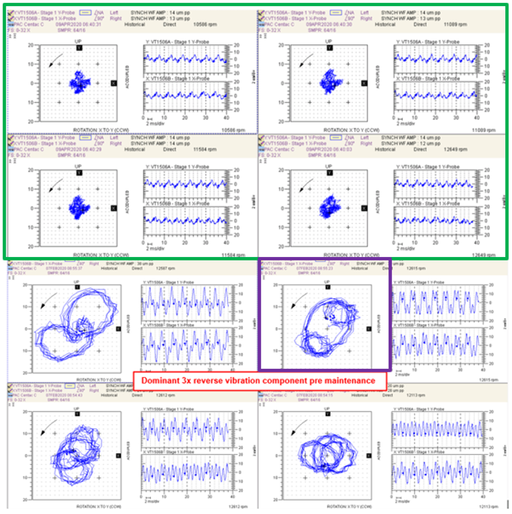
Post the repair, full spectrum asynchronous cascade and direct orbit plots verified a reduction in 1x synchronous forward vibration amplitudes during steady state operation as well as during transient events (transitioning of the 1st/translational balance resonance), as shown in Figures 10 and 11.
Post the repair the -3x reverse vibration component vibration remains with constant amplitudes measured in the region of 3 µm pp during each shutdown event. This indicates that the -3x vibration component is a characteristic of this design of Compressor rotor (P3 polygon shaped journal). It should be noted that there remains no 3x forward vibration whatsoever.
Through ongoing diagnostic evaluations (bi-monthly assessments) of the post turn-around NAP2 PAC Compressor steady state and transient vibration data, all developing machinery related malfunctions were diagnosed and reported to the client at the earliest opportunity and within the warranty period.
As the various machinery issues were diagnosed early (post the overhaul) and routinely tracked for any further progression, the plant was still able to continue to operate at full capacity until the OEM scheduled a site-based repair that was scheduled to fall within the 12-month warranty period.
Diagnostic evaluations gave the required guidance to the OEM (via the client) to ensure a full, comprehensive, and ultimately successful repair was performed, inclusive of impeller removal (this work was not part of the original OEM repair scope but on advice the integrity of the fit for 3-sided polygon impeller to journal fit was verified).
After the 1st stage stall/surge, rub and impeller to journal fit related issues were resolved by the OEM; the client was able to successfully restart the NAP2 PAC compressor, under diagnostic supervision, with no further machinery related malfunctions to report up to the present day.
Lessons learned:
- Persistent investigation into plausible sources of the increasing -3x reverse component vibration amplitudes associated with run-out continued until the OEM eventually confirmed the 3-sided polygon journal to impeller bore fit/design, which eventuated as being the root cause of one the three vibration issues.
- -3x reverse component vibration with steady amplitudes throughout the speed range during shutdown transient events was verified as a specific type of run-out, rather than a rotor dynamic issue, though the increasing amplitudes (increasing run-out) measured during consecutive shutdowns was deemed indicative of an underlying machinery issue (compromised impeller to rotor fit).
- On high-speed compressor stages the fit between the impeller and rotor/journal (three sided P3 polygon/tapered design) can be compromised by the application of anti-cease type products/compounds.
- Rotating stall/surge issues resulting in high sub-synchronous/direct vibration experienced during shutdown transient events can initiate secondary machinery related issues, in this case a 1st stage rub that resulted in a vibration (trip) event.
- Rubs, which typically occur at the locations of least clearance, can also occur internal to cylindrical and tilting pad design bearings especially if the installed bearing clearances are undersize (too tight).
- Radial bearing clearances should always be verified (mandrel check).
- Paul Goldman Ph.D., Dr Agnes Muszynska Ph.D. Orbit magazine. "Application of full spectrum to machinery diagnostic", 1999
How to Set Alarm Levels and What to Do When an Alarm Triggers
Nicolas Péton PhD, MDS Global Director
Sergey Drygin PhD, RCIS MDS Technical lead
John Yu PhD, Global MDS Technical Lead
Gary Wright, MDS Technical Lead Offline Data
David Davies, Integrity Specialist Machines for Orica Manufacturing
Egor Drygin, lyceum student
Our Experts

Gary Wright
MDS Technical Lead Offline Data
BIO
Gary Wright joined BN in 2012 as an MDS Engineer and is now the MDS Global Tech Lead for offline data. Gary has been involved in Condition Based Maintenance for 30+ years at both onshore and offshore facilities.

Sergey Drygin, Ph.D.
BIO
Sergey Drygin joined Bently Nevada in 2006 as an MDS Engineer and is now the MDS Technical Leader for RCIS and Turkey region. He has 25+ years of experience in machinery diagnostics on various types of industrial machinery. Sergey has a Ph.D. in Machinery and Technology.