

What are the characteristics of sound attenuation?
In this article:
What Is Sound Attenuation in Ultrasonic Testing?Sound attenuation is the gradual loss of energy as ultrasonic waves travel through a material, primarily due to internal absorption and scattering, which reduces wave intensity and affects signal strength.
Attenuation Depends on Material and Frequency: Different materials attenuate sound at different rates—metals generally show lower attenuation than polymers—and the effect increases with frequency, requiring careful balance between resolution and penetration depth.
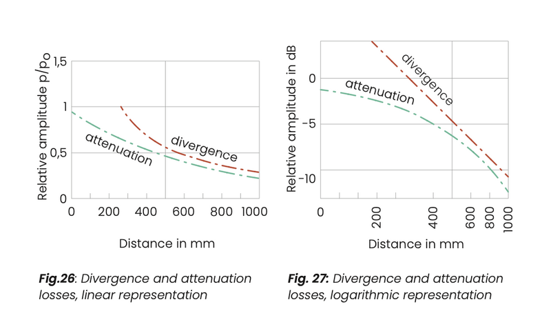
Divergence and Attenuation Losses Act Differently with Distance: While beam divergence causes intensity loss logarithmically with distance, attenuation causes a linear drop, making total signal loss a combination of both effects, especially critical in far-field evaluations.
Quantifying Attenuation Ensures Accurate Testing: The attenuation coefficient (in dB/m) is used to measure and predict signal loss, helping technicians compensate for expected weakening and ensuring reliable flaw detection across various material types.
Waygate Technologies Compensates for Attenuation with Smart UT Solutions: Waygate’s Krautkrämer ultrasonic flaw detectors and phased array systems include advanced signal processing and compensation algorithms to mitigate attenuation effects, enabling precise, repeatable inspections across a range of industrial materials.
When dealing with sound waves, especially in applications like ultrasonic testing, it's crucial to understand how sound loses energy as it travels through a material.
This phenomenon, known as sound attenuation, significantly impacts the effectiveness and range of sound-based technologies.
Sound doesn't just spread out and get weaker over distance; it also interacts with the material itself, leading to a reduction in its intensity. Let's delve into the different factors that contribute to this energy loss.
Understanding sound attenuation
It is not only the distance law, caused by the divergence of the sound beam, that ensures that no significant sound pressure is built up at large distances.
In a real material, a sound wave also constantly loses part of its energy through conversion into other forms of energy due to internal friction (absorption).
In addition, a part of the sound wave is scattered from microscopic interfaces in every direction so that a signal propagating in a certain direction also loses energy due to scatter. Both effects together are known as sound attenuation. Attenuation losses refer to the whole of the transit path of the sound wave (in echo operation 2z).
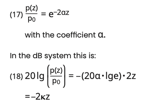
Quantifying Sound Attenuation: The Attenuation Coefficient
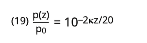
𝛋 is the attenuation coefficient in dB/m. If one transposes in equation 18 one obtains the identical decadic relationship to equation 17:
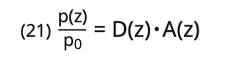
When a sound wave propagates the total loss is calculated by adding the divergence loss VD determined by the probe and the attenuation loss VA resulting from the interaction between the sound wave and the material (20):

Divergence loss and attenuation loss depend upon the distance. In general, the distance law is:
Further into the far field, where the divergence loss is described by the 1/z law, the following formula develops:
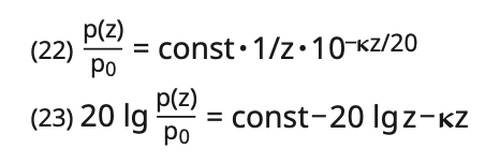
Equations (22) or (23) show that divergence and attenuation losses do not display the same distance relationship. The divergence loss is proportional to the logarithm of the distance, the attenuation loss is directly proportional to the distance z (fig. 26, 27). Electronic circuits for compensating the losses which are which are due to the distance may neither be correlated to the divergence law -Ig z nor to the attenuation law (-z) alone.
The Role of Frequency in Sound Attenuation
Basically, the sound attenuation increases with an increase in the frequency. If it is a matter of pure absorption this occurs at the square of the frequency f, and with attenuation due to scatter with even higher exponent.
This direct relationship between frequency and attenuation has significant implications for material testing. Higher frequencies provide better resolution for detecting small flaws, but they also penetrate less deeply into materials due to increased attenuation. Conversely, lower frequencies can penetrate further but offer less detail.
Some sound attenuation coefficients for different materials and at 2 MHz are shown here:
Material-Specific Attenuation: A Comparative Look
Material
Attenuation [ dB/m ]
Forged steel
< 10
Rolled steel
< 18
Casting
40 – 80
Centrifugal casting
100 – 170
PP
≈ 700
PE
≈ 700
PVC (hard)
≈ 250
PVC (soft)
≈ 3000
As you can see from the table, attenuation rates vary widely across different materials. Metals like steel generally exhibit lower attenuation, allowing sound to travel further, while polymers like PP, PE, and especially soft PVC show significantly higher attenuation. This variation is a critical factor in selecting the appropriate ultrasonic probe and frequency for a given material and application.
Further information for determining the sound attenuation and regarding its “mechanics” are given in:
[8] U. Schlengermann: Bestimmung des Schalldruckverlaufs und der Nahfeldlänge von Ultraschall- prüfköpfen mit der Mehrfach- echofolge (Determining the sound pressure function and the near field length of ultrasonic probes using the multiple echo sequence.), Materialprüfung 15
(1973) no 10, 337-341
[9] K. Lücke, D. Lenz: Ultraschall- absorption in Metallen, Neue metallkundliche Untersuchungs- verfahren (Ultrasonic absorption in metals. New methods of test- ing in metallurgy), VDI-Verlag, Düsseldorf (1970) 187-210