Advanced Radiographic Techniques with Computer Integration
In this article:
- Micro-Focus X-Ray Tubes Enable High-Precision Magnification: By using focal spots as small as 10–20 μm, micro-focus X-ray tubes allow for detailed imaging of small defects, especially when the object is placed close to the source and the detector is positioned farther away.
- Geometric Magnification Enhances Defect Visibility: The magnification factor is determined by the ratio of the focus-to-film distance (F2) to the focus-to-object distance (F1), with geometric unsharpness calculated using the formula:
Ug=Uf×F2−F1F1Ug=Uf×F1F2−F1 - Magnified Imaging Improves Resolution and Reduces Scatter: Smaller irradiated areas result in less backscatter and higher image clarity, making it easier to detect fine flaws without increasing film grain size.
- Digital Detectors and Image Intensifiers Support Real-Time Viewing: Fluorescent screens, flat panel detectors, and CCTV systems are commonly used to capture and enhance magnified images for immediate analysis.
- Trade-Offs Include Cost and Exposure Time: While magnification techniques offer superior resolution, they can be time-consuming and expensive due to the need for high-vacuum equipment and multiple exposures for large objects.
The previous sections dealt with techniques that would be impossible without the aid
of computers. These techniques share a common feature, whereby the processing, interpre-
tation and storage of data is done by a central computer and monitor, also called the work
station. In this chapter computers also play an ever increasing important role in some
of the techniques discussed. Computertomography (CT) and the Compton back scatter
technique for example would not exist without them.
With the introduction of micro-focus X-ray tubes, which have focal spots of 10-20 μm, new
special techniques have been developed.
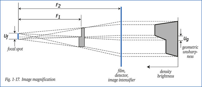
By positioning an object close to this micro-focus X-ray tube as illustrated in figure 1-17, and
by placing the film or detector at a greater distance, a magnified image is obtained. Any
defects will consequently be also magnified but still have sufficient sharpness.
Any unsharpness, as illustrated in figure 1-17, is determined by the relationship between
F1 and F2, and the size of Uf .
The effective unsharpness is calculated as follows: Ug = Uf (F2 - F1) / F1
For example:
A 150 kV X-ray tube with a focal spot size of 20 μm with focus-to-object distance (F1)
of 50 mm and focus-to-film distance (F2) of 550 mm will have a geometric unsharpness of:

Compared to standard exposures, the image magnification technique onto film using micro-
focus X-ray tubes, has the following advantages:
- Smaller defects are discernible,
- Less back scatter because a smaller part of the object is being irradiated,
- Higher resolution, as the image but not the film grain is magnified.
Disadvantages are:
- Costly if separate high-vacuum equipment is required (see section 5.1),
- Time-consuming, as for each exposure only a small part of the object is being irradiated, hence more exposures are needed.
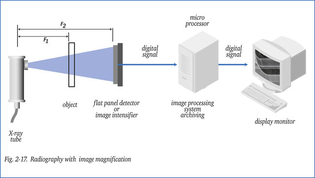
The magnification technique is mainly used in combination with a radiation-sensitive devi-
ce such as fluorescent screen, image intensifier or flat panel detector, and a CCTV-system
placed at a safe distance.
The CCTV-system can be replaced by a computer workstation for image processing and/or
enhancement prior to interpretation, as figure 2-17 shows.