How do I carry out on-stream inspection?
In this article:
- Onstream Inspection Enables Testing Without Shutdown: Onstream (or in-service) inspection allows for the evaluation of pipes, valves, and vessels during operation, using radiographic techniques to detect wall thinning, corrosion, and other defects without interrupting production.
- Projection and Tangential Techniques Are Commonly Used: The projection method captures both pipe walls in a single image, while the tangential method focuses on one wall, offering higher resolution for detecting localized thinning or damage.
- Digital Radiography Enhances Efficiency and Safety: Computed radiography (CR) with storage phosphor plates is increasingly replacing traditional film, reducing exposure times by up to 10× and minimizing required safety zones—ideal for confined spaces like offshore platforms.
- Accurate Wall Thickness Measurement Requires Calibration: To determine actual wall thickness from radiographic images, correction factors based on magnification and geometry must be applied, ensuring precise defect characterization.
- Source Selection and Exposure Settings Vary by Contents: The choice of gamma source (e.g., Iridium-192 or Cobalt-60), exposure time, and film type depends on whether the pipeline is gas- or liquid-filled, as well as its diameter and wall thickness.
On-stream inspection can be carried out on
pipes, valves, vessels, and distillation
columns while in operation, in order to establish the degree of deterioration of the
system either the projection or the tangential
technique can be used. Since the introduction of digital radiography, the CR-method
using storage phosphorplates, is increasingly
becoming an alternative for traditional film
in case of on-stream exposures, see chapter
16. The main advantage being that it reduces
the exposure time by a factor of 5 to 10, or if
lower energies (Iridium192 instead of
Cobalt60) can be applied it results in a reduced safety area, which is very attractive in
cramped spaces and personnel nearby e.g. on
offshore platforms.
Projection technique
The projection technique is most commonly
used. With this technique the two walls are
projected on film simultaneously, as shown in
figure 5-18. The image projected is larger than the actual object dimensions. It is important
to know the degree of magnification so as to be able to determine the true wall thickness.
If both walls of the pipe are projected on the film, it is straight forward to establish the correction factor, which is the true diameter (D) divided by the radiographic diameter Df .
This method should be used as much as possible.
With the projection technique, the source is placed at a certain distance from the pipe.
At a film-to-focus distance of 3 x Dinsulation and a source size of 3 mm, image quality requirement A of EN 1435 is met.
The actual pipe wall thickness (t) is equal to the
image on film (tf ) multiplied by the correction
factor (see fig. 5-18).
Most common is on-stream radiography of
insulated pipes, for which half the insulated
diameter determines the sharpness. In on-stream radiography it is important to know the
direction of the product flow, so that a existence of localised wall thickness reduction can be
better deduced. Films of 30 x 40 cm are generally used for pipe diameters up to 250 mm.
Larger diameters require more films.
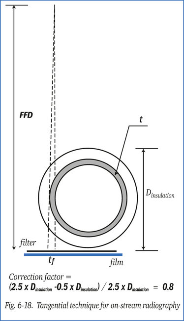
Tangential technique
In the pipe diameter range of 250 to 400 mm
the tangential technique, as shown in figure 6-
18 is sometimes applied. Only one wall is pro-
jected. The perpendicular projection produces
a sharper image. This allows a shorter focus-to-film distance, and consequently a shorter expo-
sure time. Generally, a focus-to-film distance
of 2.5 x Dinsulation is chosen.
The correction factor would then be:
(2.5 x Dinsulation -0.5 x Dinsulation) / 2.5 x Dinsulation = 0.8.
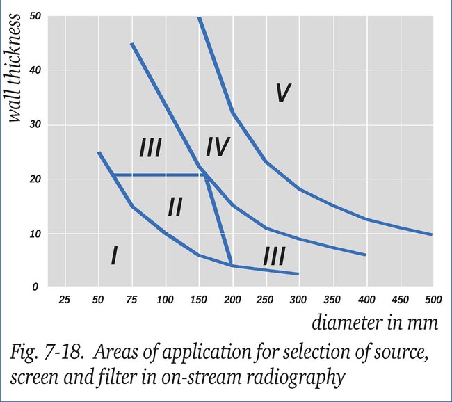
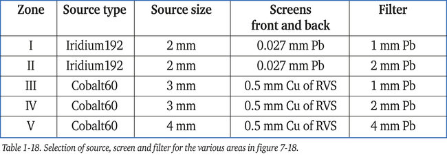
Selection of source, screens and filters
The graph in figure 7-18 indicates which radioactive source is the most suitable, depending
on pipe diameter and wall thickness. The quality of the radiograph can be optimised by
applying filters and screens, see table 1-18.
Exposure time
Obviously different exposure times are required for gas filled or liquid filled pipelines.
Below are a few examples.
For gas filled pipelines:
Depending on diameter and wall thickness : Iridium192 or Cobalt60, see figure 7-18
Focus-to-film distance : minimum 3 x Dinsulation
Irradiated thickness : 2 x nominal wall thickness
Film type : minimum C5 (EN584-1)
Film density : minimum 2.5 in the centre of the pipe projection
For liquid filled pipelines:
Depending on the diameter, wall thickness : Iridium192 or Cobalt60
Focus-to-film distance : minimum 3 x Dinsulation
Irradiated thickness : 2 x nominal wall thickness plus steel
equivalent of the pipe content
Film type : minimum C5 (EN584-1)
Film density : minimum 2.5 in the centre of the pipe projection
The steel equivalent of the pipe content is determined as follows:
(specific density in kg/m3 of content) / (specific density in kg/m3 of steel) x internal diameter
= .... mm of steel
Density of steel = 7.800 kg/m3
Density of content (oil and aqueous liquids) = 800 to 1.000 kg/m3
Notes:
- In the most commonly used insulation materials absorption is negligible.
- The long exposure times cause over-irradiation at the edge of the pipe. As a result the pipe wall shows up ‘thinner’.
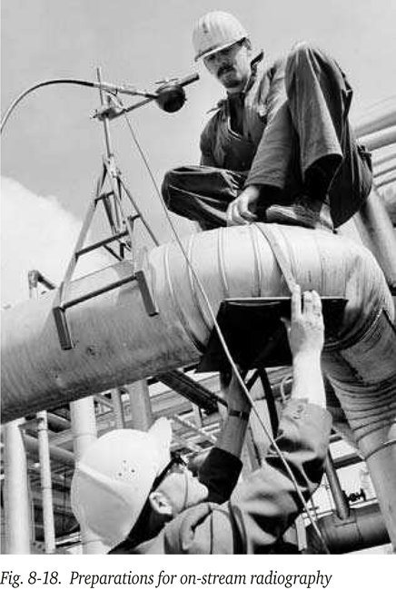
Figure 8-18 shows preparations for on-stream radiography being made. The end piece for
the gamma-source is positioned above the pipe, while the flat film cassette is placed below.
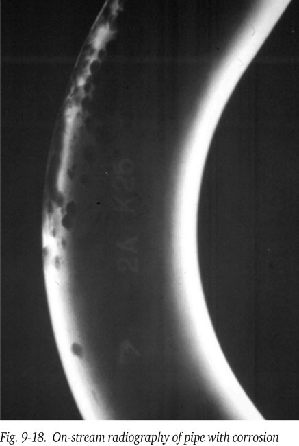
Figure 9-18 shows an on-stream radiograph of a pipe with severe pitting corrosion.
Since the introduction of digital radiography the CR-method, using storage fosforplates, is
rapidly becoming an alternative for traditional film. The main advantage being that it redu-
ces the exposure time by a factor of up to 10, or if weaker sources can be applied a reduced
safety area which is very attractive in cramped spaces e.g. offshore platforms, see the sections about Digital Radiography (e.g. this section)