Ultrasound in Materials Testing
In this article:
- Ultrasound Operates Beyond Human Hearing Range: Ultrasonic waves are mechanical oscillations with frequencies above 20 kHz, typically used in testing between 0.5 MHz and 20 MHz, enabling deep material penetration and high-resolution flaw detection.
- Sound Propagation Depends on Medium Elasticity: Ultrasound travels through solids, liquids, and gases by causing particles to oscillate; the wave type—longitudinal or transverse—depends on the medium’s ability to transmit shear forces.
- Wave Behavior Is Governed by Particle Motion and Pressure: Sound fields are described by particle displacement and pressure variations over time and space, which directly influence the electrical signals generated by piezoelectric transducers.
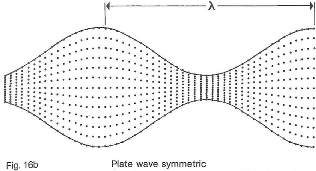
- Multiple Wave Types Can Coexist in Materials: In real-world testing, complex waveforms such as surface, plate, and rod waves emerge due to reflections and boundary interactions, complicating signal interpretation.
- Ultrasound Enables Non-Destructive Material Evaluation: By analyzing how ultrasonic waves reflect, refract, and attenuate within a material, inspectors can detect internal flaws without damaging the test object.
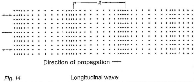
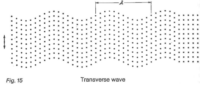
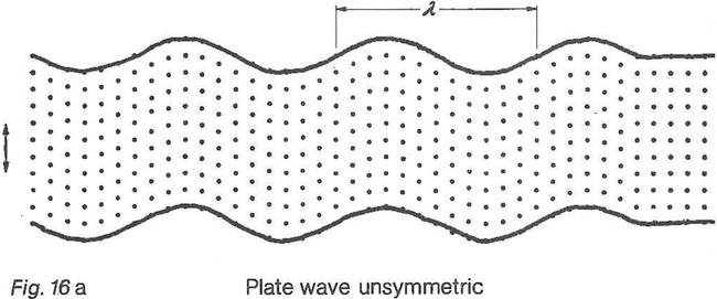
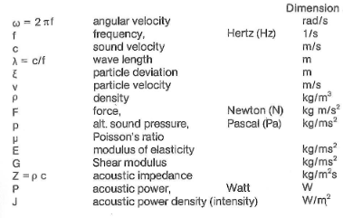
Up to now the topic was the basic properties of sound and also those of audible sound. With ultrasound the physical processes are the same as for audible sound but with the form.er the oscillations occur so rapidly that they can't be heard by the human ear. Whereas the audibility limit is approximately at 0.02 MHz ultrasonic testing uses frequencies between app. 0.5 MHz and 20 MHz (1MHz = 1000 000 oscillations per second). This property of ultrasound, 1. e. that it can be neither seen, heard nor recognized in any other way by humans admittedly doesn't sim- plify the understanding of its effects but it does have the advan- tage that, when testing, the sound intensity can be selected of such a high level that it would be unbear- able if it was in the audible range. lt is now time to describe ultra- sonic oscillations in greater detail. Any medium whether solid, fluid or gaseous can be made to oscillate. If the oscillations occur so rapidly that they lie above the human audibility limit they are referred to as being ultrasonic. lt is actually the small perfides of the medium (imagined as being elastically interconnected) which oscillate. The type of oscillation is determin- ed by the elastic properties of the medium and by the pulse which causes the medium to oscillate. The sound wave propagates in the medium at asound velocity c. One can describe the sound oscillation as amovement of the particles in the material — for example with the particle deviation = f (z, t) as function of location and time or as achange of the sound pressure p = f (z, t) with location and time. When, referring to sound pressure in materials testing, we mean the sound pres- sure which alternates with the oscillations. The sound pressure pis so impor- tant because the electric potential generated from apiezo-electric plate U = f (z, t) is directly propor- tional to the sound pressure of the impinging sound wave and vice versa. Figure 14 shows the sound propa- gation in fluid, gaseous and solid bodies. The particles oscillate in the direction of propagation of the wave. Such oscillations are called longitudinal waves. Closely pack- ed particles mean smaller devi- ation thus high particle velocity and high sound pressure. lf shear forces can be transferred in media (which is mostly the case in solids), the particles can also vibrate transverse to the direction of propagation of the wave and this is why they are known as transverse waves (fig. 15). But however such ideal cases can only exist in infinite media. lf, during atest, fef Iect ion occurs at the outer boundaries of the test specimen e. g. in plates, rods etc. complicated mixed wave forma- tions develop: plate waves, rod waves (fig. 16) and surface waves. The equations applicable to pure longitudinal and transverse waves do not apply to them. All these types of waves can be present at the same time in the test specimen and they make the Interpretation ot indications much more difficult. The most important parameters of the physics of ultrasound for materials testing are:
The following relationships exist between the different parameters:

The sound pressure then is pro - portional to the acoustic imped - ance Z, the frequency f and the particle deviation e.

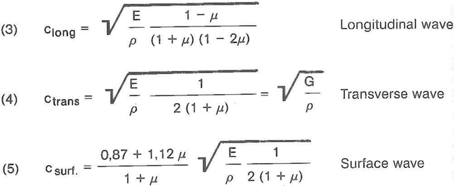
The acoustic power density J (intensity) is directly proportional to the acoustic impedance Z and the square of the frequency f and particle deviation The following relationships exist between the sound velocity cand the elastic properties: