

What are best practices with regard to the source-to-film distance?
In this article:
- Source-to-Film Distance (SFD) Directly Affects Image Sharpness: Increasing the SFD reduces geometric unsharpness (Ug), improving radiographic image clarity and flaw detectability—especially important for high-resolution inspections
- Inverse Square Law Governs Radiation Intensity: Radiation intensity decreases with the square of the distance from the source, meaning that doubling the SFD reduces intensity by a factor of four, requiring longer exposure times to maintain film density
- Optimal SFD Balances Image Quality and Practicality: While a longer SFD enhances sharpness, it also increases exposure time and equipment size, so the chosen distance must balance technical benefits with operational constraints
- Radiation Energy Selection Must Align with SFD: Once the SFD is set, the appropriate kilovoltage (kV) must be selected based on material type and thickness to ensure sufficient penetration and contrast, as outlined in exposure charts
- Gamma Source Use Requires Thickness-Specific Planning: Since gamma-ray energy cannot be adjusted, selecting the right isotope for the material thickness is essential to maintain image quality and minimize exposure time
What are best practices with regard to the source-to-film distance?
Inverse square law
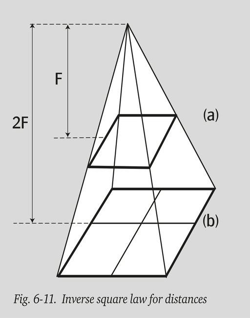
As explained in the previous section, the effect of Ug can be reduced by increasing the focus-to-film distance F. One of the properties of electromagnetic radiation is that its intensity is inversely proportional to the square of the distance, better known as the “inverse square law”. Both X - and Gamma radiation follows that law. The intensity of radiation per unit area of film is inversely proportional to the square of the source-to-film distance (s-f-d).
As figure 6-11 shows, at a distance 2F from the source, a beam of rays will cover an area (b) four times greater than area (a) at distance F. Consequently, the intensity per unit of surface area for (b) will be only 1/4 of the value for area (a). This means that, all other parameters being equal, at distance 2F exposure time must be multiplied by four to obtain the same film density.
This principle obviously has its (economical and practical) limitations, beyond which a further increase in s-f-d is just not feasible.
Selection of radiation energy (kV)
Once the appropriate source-to-film distance is chosen, the correct kilo voltage can be determined from an exposure chart (see chapter 9). The importance of choosing the exact kilo voltage varies considerably with the kilo voltage range being considered. For X-rays below 150 kV the choice is reasonably critical and gets more critical still at lower kilo voltages. The kilo voltage to be applied is specified in (EN) standards.
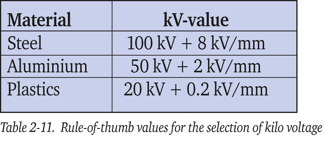
Table 2-11 gives useful empirical rule-of-thumb values for radiographs of aluminium, steel or plastic objects.
Examples :
- 15 mm steel: 100 + 15 x 8 = 220 kV
- 12 mm aluminium: 50 + 12 x 2 = 74 kV
- 10 mm plastics: 20 + 10 x 0.2 = 22 kV
In the range 200-400 kV, only a significant change in voltage, say 30-40 kV, will cause a noticeable difference in defect discernibility.
Selection of gamma source
As it is not possible to vary the radiation energy emitted by a gamma-ray source, it is necessary to indicate a range of thickness which may be satisfactorily examined with each type of radioisotope.
The upper limit is decided by the source strengths commercially available and the maximum tolerable exposure time: the lower limit is determined by the decrease in contrast and the related reduced image quality.
The lower limit, therefore, depends on the required degree of defect discernibility. When this is insufficient in comparison to what is achievable by the use of X-ray equipment, another type of isotope providing a reduced energy radiation could be selected.
Table 3-11 shows the thickness range usually recommended for various gamma sources. The table applies to steel. If, for reasons of convenience, gamma rays are used on thin specimens which could also be X-rayed, it should be understood that the resulting radiographs will be of poorer quality compared to X-radiographs.
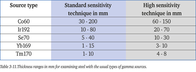
Note: Standard sensitivity permits a slightly poorer image quality than high sensitivity. Thus a larger thickness range can be inspected coping with the quality requirements.