What is determining geometric unsharpness in radiographs?
In this article:
- Geometric Unsharpness (Ug) Is Caused by Source Size and Setup Geometry: Radiographs inherently exhibit some blurring due to the finite size of the X-ray source or focal spot, which affects the clarity of defect edges in the image.
- Three Key Factors Influence Ug: The size of the radiation source, the source-to-object distance, and the object-to-film distance all determine the degree of geometric unsharpness in a radiographic image.
- Ug Can Be Calculated Using a Standard Formula: The geometric unsharpness is given by
Ug=f⋅baUg=af⋅b
where ff is the focal spot size, bb is the object-to-film distance, and aa is the source-to-object distance. - Excessive Ug Reduces Contrast and Defect Visibility: When Ug is too large, the edges of defects may overlap or blur, leading to reduced image contrast and potentially missed flaw detection.
- Minimizing Ug Requires Optimized Radiographic Setup: Using a smaller focal spot, increasing the source-to-object distance, and minimizing the object-to-film distance are best practices to reduce geometric unsharpness and improve image quality.
Three factors govern the discernibility of defects in a radiograph:
1. Geometrical effects:
- Size of the source
- Source-to-object distance
- Defect-to-film distance
2. Film properties (governing image quality):
- Graininess
- Contrast
- Fog
- Inherent unsharpness
3. Quality of radiation applied.
What is determining geometric unsharpness in radiographs?
Geometric unsharpness
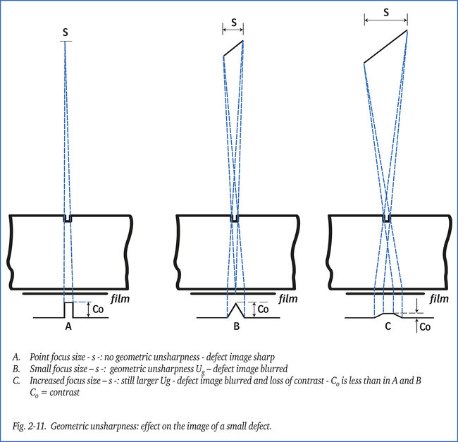
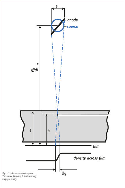
X-ray tubes and radioactive sources always produce radiographs with a certain amount of blurring – the “geometric unsharpness”, Ug in fig. 1-11, because of the finite dimensions of the focal spot or source size.
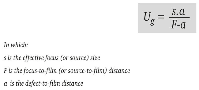
The magnitude of this unsharpness, Ug , is given in the following equation:
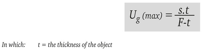
The maximum value of Ug related to a defect situated at a maximum distance from the film (and for which a = t) can be calculated from the formula:
In this situation the unsharp images of each of the two edges of the defect may overlap, as shown in example C. The result is that image C not only becomes unsharp, but also suffers a reduction in contrast compared to image A, made with a point source and image B made with a relatively small source.
Inherent unsharpness
Not only the silver halide crystals directly exposed to X-radiation are formed into grains of silver, but also (albeit to a lesser degree) the surrounding volume of emulsion. This cross-sectional area represents the “inherent unsharpness” or “film unsharpness” Uf .
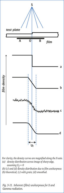
So, even in the absence of geometric unsharpness, if the radiation energy is high enough, film unsharpness can occur: the so called “inherent unsharpness”. If a steel test plate with a sharp thickness transition is radiographed with high energy X-rays, there will be a gradual transition of film density across the image of the “step” from A to B.
Without inherent unsharpness, the film would show an absolutely sharp transition between the two densities, as shown in figure 3a-11. In practice, the density change across the image is as shown in figures 3b, 3c and 3d-11.
The width of this transitional area (Uf), expressed in mm, is a measure of film unsharpness.
Table 1-11 and figure 4-11 show experimentally determined values of inherent unsharpness for film exposed at various radiation energy levels. These values are based on the use of filters and thin lead intensifying screens; thicker screens produce slightly higher values. If no lead screens are used, Uf is 1.5 to 2 times smaller. Uf is influenced mainly by radiation intensity and the type of intensifying screens used; the type of film is hardly of any consequence.
The distance between film and intensifying screen is of great importance for the value of Uf .
Good contact between film and intensifying screen is imperative and can be achieved by vacuum-packing of film and screens together.
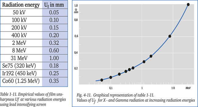
From the above information it can be deduced that Uf increases at higher radiation energies.
Total unsharpness
Total film unsharpness Ut is determined by the combination of Ug and Uf . The two values cannot be just added up to arrive at a figure for Ut .
In practice, the following formula produces the best approximation for film unsharpness Ut :

Broadly, if one value of unsharpness (Ug or Uf ) is more than twice the value of the other, the total unsharpness is equal to the largest single value; if both values of unsharpness are equal, total unsharpness is about √2 = 1.4 times the single value.
If necessary, Ug can be reduced by increasing the focus-to-film distance. This can only be done to a limited extent because, due to the inverse square law, exposure times would become extremely long. As a compromise an optimum focus-to-film distance F is chosen whereby Ug = Uf .
Consequently, Ug can be reduced to any required value by increasing the source-to-film distance. However, in view of the inverse square law this distance cannot be increased without limitation, as extremely long exposure-times would result. The formula also indicates that geometric unsharpness assumes more and more importance as the distance between defect and film increases.
A special case arises, however, when one uses a micro focus X-ray tube with a focal spot size in the range 10-50 µm. With such a small focus size, the image can be deliberately magnified by using a short source-to-specimen distance, and a large specimen-to-film distance, and still retain an acceptably small value of Ug.
The advantage of this technique, called the “projective magnification method”, is that the graininess always present in a photographic image is less of a disturbing factor in the discernibility of very small defects.
Figure 2-11 shows the effect of geometric unsharpness on the image of a defect smaller than the focus size.