Ultrasonic Testing Equipment: Components and Principles
In this article:
- Pulse-Echo Is the Core Technique in Ultrasonic Testing: The pulse-echo method uses a single probe to emit ultrasonic pulses and receive echoes reflected from internal flaws or material boundaries, enabling non-destructive evaluation.
- Key Components Include Pulse Generator, Probe, and Amplifier: The system consists of a pulse generator, piezoelectric probe, amplifier, and evaluation unit, all working together to transmit, receive, and process ultrasonic signals.
- Echo Timing and Amplitude Reveal Flaw Location and Size: The time delay between pulse emission and echo reception determines the depth of a reflector, while echo amplitude helps assess flaw size and severity.
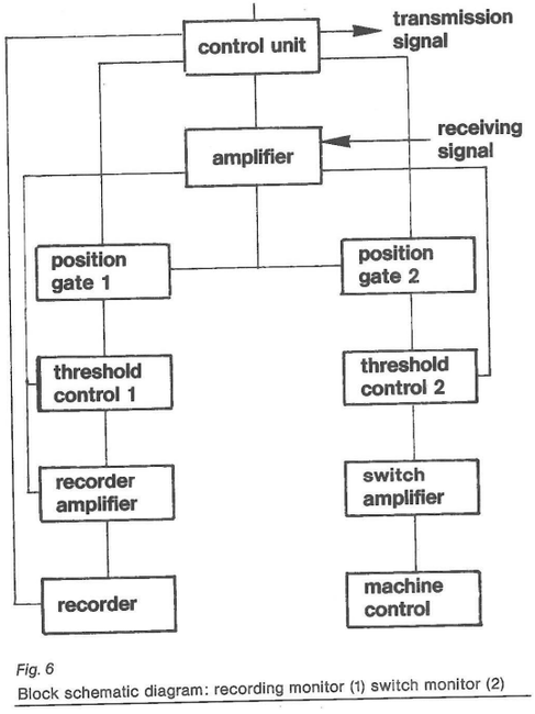
- Gate Circuits and Thresholds Enable Automated Evaluation: Gate circuits monitor specific time windows, and threshold levels classify signals, allowing for automated flaw detection and digital signal processing.
- Accurate Synchronization Prevents Signal Overlap and Errors: Proper timing between pulse repetition and probe movement is critical to avoid missed or duplicated reflectors, ensuring reliable and reproducible test results.
The purpose of ultrasonic equipment used in the pulse-echo technique is to make the difference between " sound Input" and "sound output" technically measurable 1. e. so that it can be evaluated. Be it a simple battery operated Instrument or a test Installation with automatic evaluation and control the same components are always used.
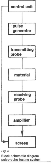
3.1 Controlling unit. This unit determines the sequence of the testing cycle 1. e. when to transmit and when to receive and evaluate.
3.2 Pulse generator. Generates the pulse which induces the probe to oscillate mechanically.
3.3 Probes. The probe transforms the electrical pulses into mechanical oscillations (ultrasound) and vice versa, converts sound oscillations into electrical ones. The transmitter and receiver probes can be identical (single- probe operation) or separate (TR-operation, tandem-operation).
3.4 Amplifier. The amplifier amplifies and filters the signal received and transformed by the probe. The gain can be either linear or logarithmic.
3.5 Evaluation. Sometimes it has already been done by the gain characteristic. Normally the signals are classified into signals which are either lower or higher than a threshold level. The Instrument which does this is known as the monitor.
3.6 Output. Here the converted and evaluated received signal can be processed further in accordance with a pre-selected program and can be either printed, displayed or stored.
Fig. 5 shows the basic layout of ultrasonic equipment which converts the incoming signal, amplifies it and then displays it on the screen. In automatic installations the screen is mostly replaced by a more suitable unit. Fig. 6 shows the principle of a monitor circuit for evaluating indications according to their amplitudes and transit times. A gate circuit monitors a specific transit time range. If the amplifier delivers a signal within this time range the signal can, for example, be converted again, by a recorder amplifier and then be evaluated either analog or digital.
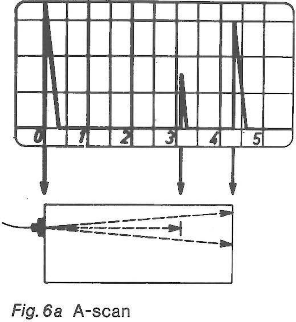
Instead of a recorder amplifier the YES/NO output of the threshold circuit can be routed through an interface amplifier which generates signals used for controlling the testing process. When testing lt is very important to note the relationship between the pulse repetition frequency and test cycles (movement of the probe and/or test specimen etc.) If this time relationship is not considered lt would result in considerable errors, 1. e. overlooking reflectors in the material and the multiple counting of reflectors, in the best data output although all parts of the system function perfectly and the results are reproducible. The documentation of the test results is just as varied as is the number of testing problems. With Instruments used for manual testing lt is usual to have a CRT or LCD screen upon which the signal amplitude is displayed above the transit time in the form of an A-scan (fig. 6a). A display is also possible here by means of an array of diodes. lf, on the screen, the location of the reflector is only given by two dimensions then one has a Cscan. Printing strips, and plots which are adequate to the C-scan are also often used as information storage (fig. 7).