Smart inspection of rail wheels with matrix arrays
Thomas WÜRSCHIG, Andreas FRANZEN, Frank HENRIX, Frank KAHMANN, Prashanth Kumar CHINTA, and Daniel WERNER
In this article:
- Revolutionizing Rail Wheel Safety with Matrix Arrays: The article introduces advanced ultrasonic testing (UT) using matrix array probes, enhancing the detection of both surface and volumetric defects in critical rail wheel components.
- Comprehensive Coverage of Complex Geometries: Matrix arrays enable full inspection of wheel faces, flanges, webs, and treads, overcoming challenges posed by diverse wheel shapes and wear patterns.
- Efficiency Through Automation and Robotics: Integration with robotic systems reduces inspection time to as little as 6 minutes per wheelset, supporting high-throughput rail maintenance operations.
- Smart Inspection Aligned with NDT 4.0: The solution supports digital twin creation and automated defect recognition, aligning with Industry 4.0 standards for predictive maintenance and lifecycle tracking.
- Enhanced Reliability and Flexibility: Matrix probes reduce the number of required transducers, improve coupling conditions, and allow for adaptive inspection setups, even on large-diameter wheels.
Smart inspection of rail wheels with matrix arrays
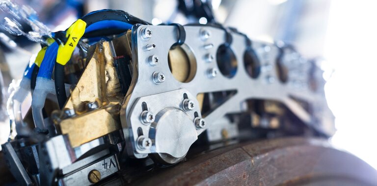
Rail wheels are one of the most safety critical safety components of rolling stock. Any failure can lead to catastrophic events resulting in high material damage and personal injury or even fatalities. Therefore, international railway standards require non-destructive inspection by means of ultrasound testing (UT) on a regular basis. Due to increasing distances, loads and speeds there are increasing demands on the precision and the scope of testing. However, the inspection of train wheels is complicated due to the large variety of wheel geometries and the further influence of different milage. Moreover, extended inspection areas up to a full body inspection define many different defect positions, which are to some part difficult to access. This article describes industrial solutions, which allow the full-body inspection of train wheels including face, flange, web and tread for volumetric defects (from 2mm diameter) and surface cracks (from 5 mm length and 1 mm depth). In the latest upgrade, these systems can be now equipped with matrix probes. At the beginning of the article basic principles and general probe configurations will be discussed. The main part of this article is then dedicated to highlight the positive impact of the implementation of matrix probes. Besides a reduction of the form factor due to the decreased number of probes, matrix probes allow a direct coupling check thus fundamentally amending the existing state-of-the-art. Other advantages refer to improved settings for a higher reliability of the system. Finally, it is outlined in which way matrix probes provide additional functionalities to extend the current state-of-the-art towards a smart inspection.
1. Introduction
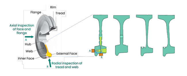
Larger networks, higher loads, and increased speeds in the railway sector are posing big challenges to implement appropriate safety standards. In this context, rail wheels represent one of the most critical components. Here, the situation is currently aggravated by difficulties in the new procurement of wheels due to bottlenecks in the supply chains, which necessitate longer lifecycles of used train wheels. According to global railway standards, ultrasonic inspection is performed not only after production but also during service on a regular basis [1-3]. In this way it should be ensured to detect material defects at an early stage and to trigger safety procedures before accidents due to material fatigue can emerge. However, wheel failures still occur [4,5]. For example, just recent incidents causing significant material damage revealed that an existing crack could propagate over time without being detected [6,7]. Therefore, it is obvious that the existing standards need to be extended, including the mandatory inspection of the wheel disk in addition to sole measurements on the treat and the rim. As illustrated in Fig. 1, the inspection task of train wheels is challenging due to the complex geometry. In most cases there are different wheel geometries for the same train type which are, moreover, influenced by the milage of the wheels. To cope with these demanding tasks at a large scale, an adaptive system is required, which can be only achieved by an appropriate probe configuration in combination with advanced PAUT methods. For the latter, the implementation of matrix probes will play a crucial role. This article illustrates patented methods [8-10] referring to the use of matrix array and summarizes results obtained for the measurement from the tread and the face.
Fig. 1 Access to different wheel parts (left) and typical examples of different wheel geometries (right)
2. Principles and methods
In principle, there are two probes positions that can be used either for disassembled wheels or wheelsets as well as for assembled wheelsets on the train. Fig. 2 gives an overview about typical configurations. The radial inspection is applied for the tread and web, the axial inspection gives access to face and flange of the wheel rim. While longitudinal waves with perpendicular incidence are used for volumetric defects, cracks are detected by angle beams from two opposing sound directions I and II. For the radial and tangential crack orientation in the web the inspection is performed with pulse echo and dual probe technique, respectively. A large angular range must be covered to ensure full coverage. Therefore, it is necessary to implement phased array technology to keep a reasonable form factor. The number of probes can be reduced by operating the radial probes (a, b and a’,b’ in Fig. 2) both in pulse echo and dual probe mode.
Fig. 2 Schematic illustration of typical probe arrangements for the inspection of train wheels

3. Industrial solutions
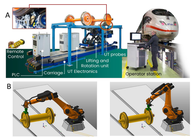
Train wheels need to be inspected regularly either in operation or disassembled after production or during major maintenance intervals. Fig. 3, at top, illustrates an industrial solution for the onsite rail wheel inspection as it is well-established for instance for highspeed trains in Germany [11]. While in this setup the ultrasonic probes are coupled from below, latest robotic solutions for disassembled wheelsets attach the test mechanics from above thus reducing the overall space requirements and taking advantage of improved coupling conditions. The typical net inspection time per wheel is around 90 seconds. A complete wheelset inspection of web, tread, rim, inner and external face takes typically not more than 15 minutes, including changeover, analysis and reporting. Even faster inspection intervals of 6 min can be reached in case of robotic solutions. An assistive, multi-layered analysis including, e.g., automated defect recognition and geometry echo suppression [12], supports the operator in the final decision. The overall inspection concept implements all basic concepts needed for NDT4.0 [13]. In particular, the creation of a digital twin allows the tracking of wheelsets over the full lifetime. As latest upgrade, both illustrated systems can be equipped with matrix probes benefitting from powerful electronics, which allows a flexible operation and the application of advanced PAUT methods also for large apertures [14].
Fig. 3 Industrial solutions for in-line train wheel inspection (A) and disassembled train wheels (B)
4. Implementation of matrix technology
4.1 Reduced number of probes and probe types
In the current state-of-the art, 1D array probes are already used to cope with the demanding test task for wheel inspection. However, while a flexible electronic steering is possible in one direction, the second angle is still fixed. Therefore, a separate pair of probes is needed to inspect the inner and outer surface of the web, respectively. For the same reason, four probes are needed to be attached from the face to inspect cracks at the rim and the flange. In contrary, the big advantage of matrix probes is the electronic steering within the full solid angle, i.e. of the vertical and horizontal angle (βV and βH and Fig. 2). It is thus possible to achieve the same test functionality which much less probes. The decreased form factor allows a very compact design, which is of particular interest for robotic and mobile solutions. Moreover, the use of matrix probes reduces not only the number of probes but also the number of different probe types because it is possible to mimic different wedge geometries as currently applied in the testing machines.
4.2 Direct coupling check
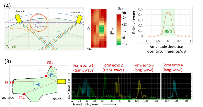
To date, one of the major challenges for any wheel detection is the coupling control because in most cases there are no appropriate form echoes available. Due to the direct contact techniques even the usage of the interface echo is excluded. Therefore, all existing approaches are based on indirect measurements either by a noise analysis or the transfer of the results obtained with additional probes dedicated to accessible form echoes. The use of matrix probes can bridge this gap because it is now possible to adjust the beam angle towards an accessible form echo and thus directly check the coupling quality. Possible options are shown exemplarily in Fig. 4. Due to the optimized settings the introduced coupling check is extremely precise. The maximum fluctuation of the coupling signal for radial probes over the full circumference typically stay well below ±0.5dB.
Fig. 4 Direct coupling check for radial (A) and axial inspection (B)
4.3 Optimized machine settings
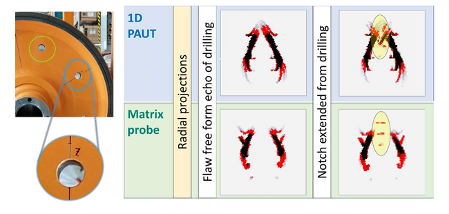
As discussed above, one of the main advantages of matrix probes is the electronic setting of the second angle. Therefore, besides a high precision coupling check it is also possible to optimize the sensitivity for each defect type and for different wheel geometries independently. One example of such optimization for radial probes is shown in Fig. 5. The value range for the second angle (βH) is in between 2° and 12° with opposing trends for radial and tangential defects. Consequently, in current setups a compromise must be found between an optimum setting for radial defects (small angles) and tangential defects (large angles). The improvement with matrix probes results in lower gain values and avoids false calls. It has also a direct impact on the quality of the projection image (see Fig. 6).
Fig. 5 Result of the optimization for the horizontal steering angle (βH) for the radial inspection obtained for two different wheel types. Large difference of 8° to 10° occur for same defect types at different depth and between different defect types.
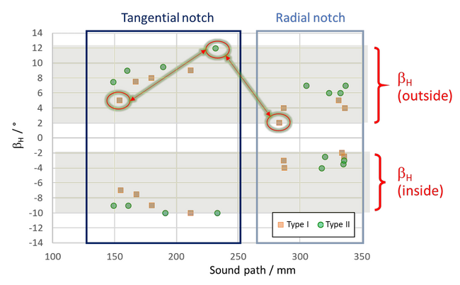
Fig. 6 Improved projection data obtained after optimization for the horizontal steering angle (βH). In case of matrix probes, the radial notch in extension of the hole is clearly visible. In current state-of-the art, operators need to further analyze the acquired data (A-Scan and TD-scan) to clearly identify the defect.
4.4 Increased functionality
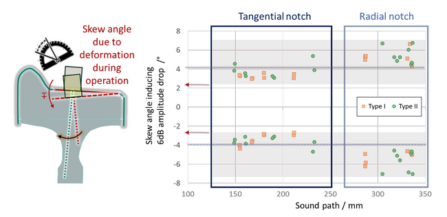
Beyond the sole optimization of the current state-of-the art, matrix probes also give access to an increased functionality. In this context, electronic steering to circumferential form echoes can be used to identify the inspected wheel type (see Fig. 7). Most promising and relevant for daily applications is the onsite condition measurement for the inspected wheelset which allows for a direct compensation. One example is the extraction of the additional skip angle of worn tread which leads to a decreased probability of detection in case of assuming the nominal profile (see Fig. 8). Another option taking benefit from the high-precision coupling check is given by a gain transfer correction for the test channels of the axial probes, which considers the rather strong deviations of the coupling conditions from the face.
Fig. 7 Recognition of wheel type in the angular response pattern of the form echo from the transition of the tread to the rim.

Fig. 8 Extracted skew angles for a 6dB amplitude drop for radial and tangential notches in the web at different depths. Mean values range between 3° and 7°. Onsite measurements allow the determination of the current skew angle, which is related to the deformation during operation, and an electronical compensation to remain with the same probability of detection.
5. Conclusions
Increasing inspection demands in the rail sector will imply the need for a reliable test system coping with a large variety of wheel geometries. In this context, the implementation of matrix probes provides the highest flexibility to adapt to different test setups and facilitates the overall setting for the operator. In particular, the use of matrix probe allows a direct coupling control thus closing an existing gap in the current state-of-the-art. In combination with the possible optimization for each defect type and for different wheel geometries, the matrix technology enables highly reliable measurements and decreases falls calls, which are connected to high avoidable costs. Furthermore, the implementation of matrix probes gives access to additional functions such as an automated recognition of the wheel type and the measurement and compensation of the wheel conditions at the time of inspection. These features deliver the input needed for a real smart inspection.
References
[1] EN 13262, “Railway applications - Wheelsets and bogies - Wheels - Product requirements”, CEN (2020) [2] ISO 5948:2018, “Railway rolling stock material - Ultrasonic acceptance testing”, ISO (2018) [3] MxV Rail, “Manual of Standards and Recommended Practices: Section G-II, Mandatory and recommended shop practices for wheel and axle shops”, Association of American Railroads (2022) [4] European Union Agency for Railways, “Report on Railway Safety and Interoperability in the EU”, ISBN 978-92-9477-411-8 (2022) [5] U.S. Department of Transportation, “Wheel Failure Investigation Program: Phase I”, Federal Railroad Administration (2022) [6] Transportation Safety Board of Canada, “Rail transportation safety investigation report R18W0007”, ISBN: 978-0-660-33092-1 (2019) A. Schweizerische Sicherheitsuntersuchungsstelle, “Zwischenbericht der Schweizerischen Sicherheitsuntersuchungsstelle SUST über die Entgleisung eines Güterzuges im Gotthard-Basistunnel”, Swiss Confederation (2023) [7] S. Falter, A. Franzen, F. Henrix and D. Werner, “Ultrasonic testing inspection with coupling validation”, WO2019075347A1 (2019) [8] A. Franzen, F. Henrix and D. Werner, “In-service high speed rail wheel testing”, EP3739330A1 (2020) [9] A. Franzen, F. Henrix, D. Werner, “Methods and devices for ultrasonic non-destructive testing devices”, WO2021202143A1 (2021) [10] D. Werner, T. Würschig, “In-Service Ultrasonic Wheel Inspection thought beyond - New Generation with Focus on improved Ergonomics, Digitalization and Operator Support”, 13th European Conference on Non-Destructive Testing 2023. e-Journal of Nondestructive Testing Vol. 28(8). (2023) [11] S. Falter, T. Heckel and U. Völz,“Device and method for determining material faults in rotationally symmetrical test samples by means of ultrasound”, EP2821783A1 (2015) [12] D. Werner, A. Franzen, F. Henrix, U. Phillips, P. Buschke, “Digitalization for RailwayNDT”, 2nd European NDT & CM Days, Oct 4-7, Prague, Czech Republic (2021) [13] Waygate Technologies, “High-End Electronics Platform for Ultrasonic Testing Machine USIP|xx”, Data sheet, BHCS38592 (2020)
